


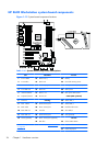
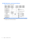
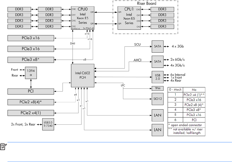
HP Z620 Workstation system board architecture
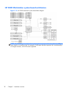
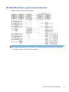
Figure 1-20 System board block diagram
NOTE: The PCIe designators indicate the mechanical connector size and number of electrical PCIe
lanes routed to an expansion slot. For example, x16 (8) means that the expansion slot is mechanically
a x16 length connector, with 8 PCIe lanes supported.
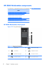
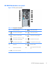
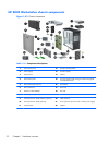
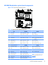
HP Z620 Workstation components
27