


Dimension / Wiring Diagrams
288 CSI Section 16160
Siemens Electrical Products and Systems
Specification Guide
AC Controls
15
AC Controls
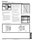
Manual Motor Starter Switches
Application
Class 12 manual starting switches are
designed to economically start and stop
inherently protected single and polyphase
motors as used in light machine tools,
pumps, blowers, and vent-fans. They are
also used as ON and OFF switches for
resistive loads such as heating.
Features
This switch is compact, economical, and
easily wired using pressure type screw
connectors. A rugged over center toggle
mechanism results in a long life with
weld free operation. It is available for sur-
face mounting in a NEMA 1 enclosure,
for flush mounting on a standard depth
switch box or in custom panels. A pilot
light for 120, 208 / 240, or 480 volts may
be added at any time before or after
installation.
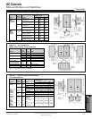
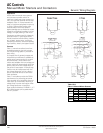
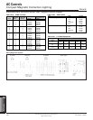
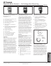
Wiring Diagrams
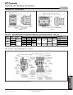
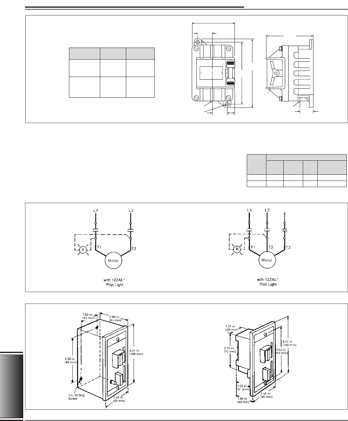
Dimension Drawings
1-Phase
3-Phase
NEMA 1
Open with Flush Plate
Type
1-Phase
3-Phase
2
230–
575
Volts
115
Volts
120V
DC
Continuous
Amp Rating
3241
——
215
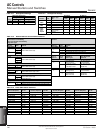
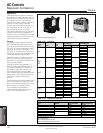
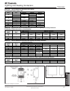
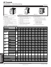
Table 15.9
Class 12 Manual Starting Switches
Maximum Horsepower
Device
Type of
Operator
Toggle
Toggle
Class SMF
Fractional
HP Starter
Class MMF
Motor
Starter
Switch
FR2, FR2H
FR1, FR1H
KR2, KR2H
KR2, KR1H
Type
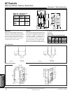
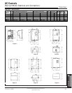
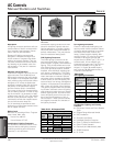
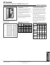
Table 15.8 Explosion Proof
NEMA 7 & 9 Enclosures
1.19 in.
(30.23 mm)
0.75 in. -14
(19.05 mm)
Pipe Tap
(Bottom Only)
9⁄32
Padlock
Hole
0.72 in.
(18.29 mm)
1.38 in.
(34.93 mm)
Center Line
(Conduit)
0.31 in.
(7.94 mm)
Mtg. Holes
4.38 in.
(111.25 mm)
3.97 in.
(100.8 mm)
1.38 in.
(35.05 mm)
6.38 in.
(162 mm)
5.75 in.
(146 mm)