


●
Speakers (see
Speakers on page 61)
●
USB board (see
USB board on page 63)
●
Power connector cable (see
Power connector cable on page 64)
●
Display assembly (see
Display assembly on page 66)
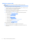
NOTE: When replacing the system board, be sure that the following components are removed from
the defective system board and installed on the replacement system board:
●
Memory module (see
Memory module on page 45)
●
RTC battery (see
RTC battery on page 78)
●
Fan/heat sink assembly (see
Fan/heat sink assembly on page 80)
●
Processor (see
Processor on page 86)
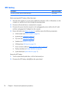
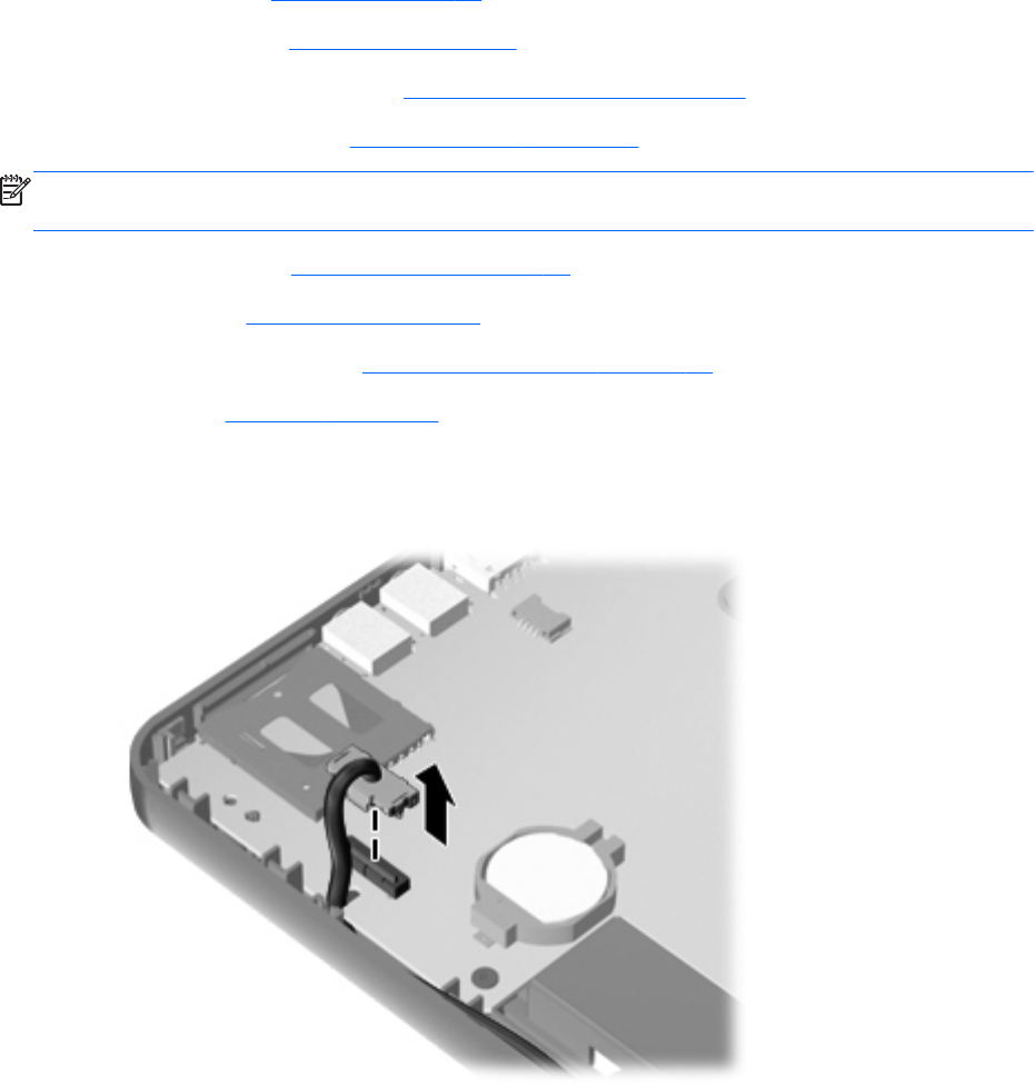
Remove the system board:
1.
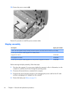
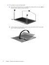
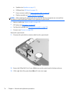
Disconnect the optical drive connector cable from the system board.
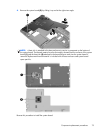
2. Remove the Phillips PM2.5×6.0 screw (1) that secures the system board to the base enclosure.
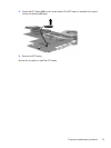
3. Lift the right side of the system board (2) until it rests at an angle.
74 Chapter 4 Removal and replacement procedures