Important Safety Information
Before installing the product, read the Important Safety
Information guide included with the packaged cluster.
WARNING: To reduce the risk of personal injury
or damage to the equipment:
Observe local occupational health and safety
23137 kg requirements and guidelines for manual
50300 lb material handling.
Obtain adequate assistance to lift and stabilize
the chassis during installation or removal.
Audience Assumptions
This poster is for the person who installs, administers, and
troubleshoots clusters. HP assumes you are qualified in the
servicing of computer equipment and trained in recognizing
hazards in products with hazardous energy levels. For detailed
instructions, refer to the packaged cluster documentation CD.
Legal Notice
© 2003 Hewlett-Packard Development Company, L.P.
Microsoft and Windows are trademarks of Microsoft Corporation in the U.S. and
other countries.
Hewlett-Packard Company shall not be liable for technical or editorial errors or omissions
contained herein. The information in this document is provided "as is" without warranty of
any kind and is subject to change without notice. The warranties for HP products are set
forth in the express limited warranty statements accompanying such products. Nothing
herein should be construed as constituting an additional warranty.
Third Edition (January 2003)
Part Number 252657-003
hp ProLiant DL380
generation 3
packaged cluster
hardware installation and
configuration poster
Getting Started
Smart Array Cluster Storage
Front Panel Components
Item Description
1 Bezel blank (bay for optional redundant controller)
2 Service port (for HP service technicians only)
3 Hot-plug Smart Array Cluster Storage Controller
4 Controller display
5 Power On/Standby button
6 Enclosure LEDs
7 Hot-plug SCSI hard drives
Enclosure LEDs
Item LED Description Status
1 Shared Storage Module Flashing green= Module is
operating normally.
Green/Off = Module is not
operating normally.
2 System power Green = System power is on.
Off = System is in standby
mode or power is removed
from the system.
3 Fault Amber = Fault detected in a
subsystem.
Off = No faults detected.
Rear Panel Components
Item Description
1 Interconnect blanks (required for proper airflow)
2 Power supply/blower assembly
3 AC power connectors
4 2-Port Shared Storage Module
2-Port Shared Storage Module LEDs
Item LED Description Status
1 Power Green = Power on
Off = Power off
2 SCSI host port A Flashing green = On/Activity
Off = Off
3 SCSI host port B Flashing green = On/Activity
Off = Off
Setup in the
Configuration Fixture
Perform the following procedures for setup of the packaged
cluster in the configuration fixture. This setup procedure
assumes the cluster will be configured in the fixture and then
transferred to another location.
WARNING: Do not stack clusters while in their
configuration fixtures. The stack can become unstable
and may tip over.
1 Installing Hardware Options
NOTE: Detailed option installation instructions are available with the
options and are also in the server setup and installation guide, the
server supplemental setup guide, and the storage system user guide
on the Documentation CD.
1. If internal server options (memory, processors, fans, and
expansion boards) need to be installed:
a. Remove the servers from the server fixture.
WARNING: To reduce the risk of personal injury or
damage to the equipment, the server must be completely
removed from the server fixture to install the internal
server options. At least two people are required to lift the
servers during installation or removal.
b. Install the internal server options.
c. Replace the servers in the server fixture.
2. Install the external server options.
3. Install the external storage system options.
2 Cabling the System in the
Configuration Fixture
NOTE: The server fixture should be placed on top of the storage
system fixture for ease in cabling the packaged cluster.
1. Connect the VHDCI SCSI cables labeled A and B from the
storage system to the servers.
IMPORTANT: Save the protective covers on the cable connectors
for use when the packaged cluster is repacked.
2. If you are configuring a Microsoft or Linux operating
system, connect the Ethernet crossover cable between the
servers. Use the same RJ-45 connector (1), NIC 1, on each
server.
3. Connect the peripheral devices such as the keyboard,
mouse, and monitor. For information on peripheral device
connections, refer to "Component and LED Identification"
on this poster.
WARNING: To reduce the risk of electric shock, fire, or
damage to the equipment, do not plug telephone or
telecommunications connectors into RJ-45 connectors.
IMPORTANT: If the Remote Insight Lights-Out Edition II (RILOE II)
board is installed in the server, be sure that you can attach the
video cable to the video connector on the rear of the RILOE II
board. The standard video connector on the server rear panel is
not used when the RILOE II board is installed. For more information,
refer to the HP Remote Insight Lights-Out Edition II User Guide on
the Documentation CD.
NOTE: If you are using a KVM switchbox, refer to the switchbox
documentation for detailed instructions.
4. Connect the power cords to the servers and storage system.
3 Powering On and Configuring
the Packaged Cluster
1. Power on the storage system (1) and wait for the controllers
to initialize.
IMPORTANT: You must power on the Smart Array Cluster Storage
system before powering on the servers. After powering on, wait
until the storage system startup complete message displays. It might
take up to two minutes for the system to completely power up.
2. Power on one server, (2) or (3).
IMPORTANT: Do not use the Option ROM Configuration for Arrays
(ORCA) utility to configure the Smart Array Cluster Storage. The
Array Configuration Utility must be used.
While the server boots, the ROM-Based Setup Utility (RBSU)
and the ORCA utility are automatically configured to prepare
the server for the operating system installation. To configure
these utilities manually:
Press the F8 key when prompted during the array
controller initialization to configure the array controller
using ORCA.
Press the F9 key when prompted during the boot
process to change the server settings, such as the
settings for language and operating system, using
RBSU. The system is set up by default for the English
language and a Microsoft Windows 2000 installation.
For more information on the automatic configuration, refer to the
HP ROM-Based Setup Utility User Guide located on the
Documentation CD.
3. Insert the SmartStart CD into the CD-ROM drive and reboot
the server. Follow the on-screen instructions to begin the
operating system installation process.
For more information on installing the operating system,
refer to the SmartStart installation poster included in the
ProLiant Essentials Foundation Pack, the HP ProLiant DL380
Generation 3 Packaged Cluster Setup and Installation
Guide, or the operating system documentation.
4. Repeat steps 2 and 3 for the second server.
5. Set up and verify the Smart Array Cluster Storage system
and cluster operations.
IMPORTANT: For detailed information on completing the cluster
setup, refer to the HP ProLiant DL380 Generation 3 Packaged
Cluster Setup and Installation Guide located on the Documentation
CD.
NOTE: Updated installation and cluster setup information is
periodically released in HP white papers. Go to
www.hp.com/servers/proliant/highavailability
for the most recent information.
4 Powering Down and Preparing
for Transfer
1. Shut down the operating system on each server and power
off each server.
2. Power off the storage system.
3. Remove the power cords and return them to the original
boxes.
4. Disconnect the VHDCI SCSI cables and the Ethernet
crossover cable from the servers.
5. Disconnect all other cables from the servers.
6. Replace the protective covers on the ends of the VHDCI
SCSI cables.
7. Secure the VHDCI SCSI cables and the Ethernet crossover
cable for transfer.
8. Repack the shipping components in their original
configuration. Refer to the exploded view diagram and
pictures on the packaged cluster poster as a guideline
for repacking.
Configuration is complete. The packaged cluster is ready
for transfer.
See other side of poster for setup and installation in a rack.
252657- 003
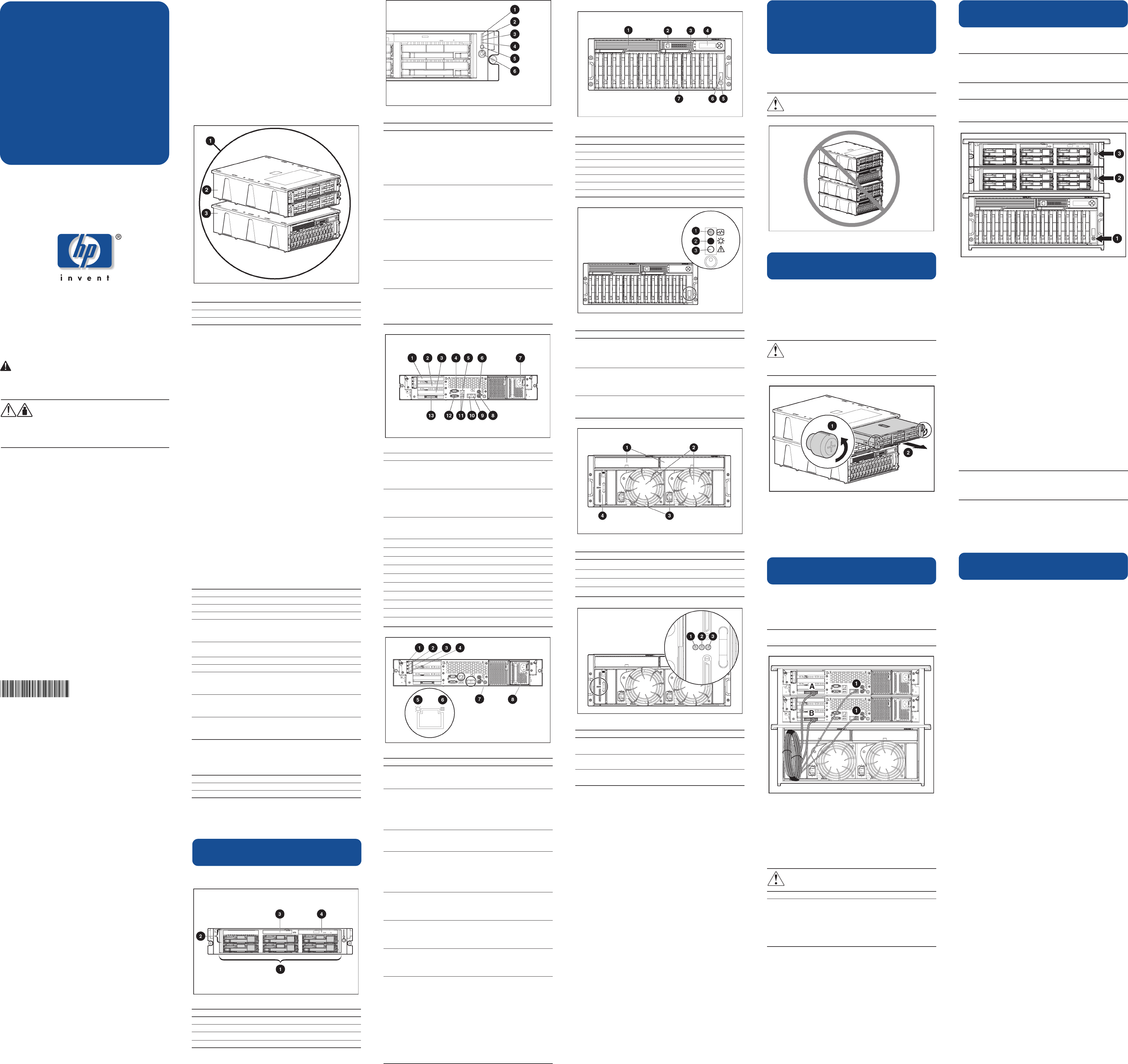
Poster Overview
This poster covers the following:
Component and LED identification
Setup in the configuration fixture
Setup and installation in a rack
HP ProLiant DL380 Generation 3
Packaged Cluster
The packaged cluster ships in a two-piece configuration fixture.
The server fixture holds the two ProLiant DL380 Generation 3
servers. The storage system fixture holds the Smart Array Cluster
Storage system.
Item Description
1 Two-piece configuration fixture
2 Server fixture
3 Storage system fixture
NOTE: The server fixture and the storage system fixture are
environmentally safe and recyclable. The configuration fixture
should be recycled in accordance with your local recycling
center guidelines.
Setup Preparations
Required Materials
Before setting up your packaged cluster, locate the following
materials included in the shipping box:
ProLiant DL380 Generation 3 servers
Smart Array Cluster Storage system
Power cords and cables
Rack mounting hardware and rack templates (not used
with the configuration fixture)
HP SmartStart CD
Hardware documentation and software packs
Locate the following materials not included in the packaged
cluster shipping box:
Hard drives
Server hardware options and documentation (optional)
Storage system hardware options and documentation
(optional)
Keyboard, monitor, and mouse (need two of each if not
using a switchbox)
Keyboard, video, and mouse (KVM) switchbox (optional)
Operating system CDs
Required Information Checklist
Gather the following information (dependent on the operating
system).
Server node names
Server node IP addresses and subnet masks
Cluster name (Microsoft and NetWare only)
Cluster IP address and subnet mask
IP addresses and subnet mask for the cluster interconnect
(Private network used for intracluster communications)
(Microsoft and Linux only)
Server node administrator password for each server (used
during operating system installation)
New or existing NDA Tree (NetWare only)
Domain name (Microsoft only)
Domain administrator user name and password (used during
operating system installation to have the server node join the
domain) (Microsoft only)
Domain account name and password for cluster service (this
account has special privileges on each cluster server node)
(Microsoft only)
Other network settings as needed for your operating system (for
example, default gateway address, WINS server address, and
DNS settings)
Selecting an Appropriate Site
Select an installation site that meets the following requirements.
Space Temperature
Power Rack
Grounding Airflow
Detailed installation site requirements are described in the
server user guide on the Documentation CD.
Component and LED Identification
ProLiant DL380 Generation 3 Server
Front Panel Components
Item Description
1 Hard drive bays
2 Bay for tape drive or hard drive and tape drive blank
Front Panel LEDs and Buttons
Item Description Status
1 Internal health LED Green = Normal
Amber = System degraded.
Refer to system board LEDs
to identify component in
degraded state.
Red = System critical. Refer to
system board LEDs to identify
component in critical state.
2 External health LED Green = Normal
(power supply) Amber = Power
redundancy failure
Red = Critical power
supply failure
3 NIC 1 link/activity LED Green = Network link
4 NIC 2 link/activity LED Flashing = Network link
and activity
Off = No link to network. If
power is off, view the rear
panel RJ-45 LEDs for status.
5 UID LED button Blue = Activated
Flashing = System remotely
managed
Off = Deactivated
6 Power On/Standby Green = System on
button/system power Amber = System shut down, but
LED power still applied.
Off = Power cord not attached
or power supply failure.
Rear Panel Components
Item Description Connector Color
1 Hot-plug PCI-X N/A
expansion slot 3
(bus 6) 64-bit/
100-MHz 3.3v
2 Hot-plug PCI-X N/A
expansion slot 2
(bus 6) 64-bit/
100-MHz 3.3v
3 Non-hot-plug PCI-X N/A
expansion slot 1 (bus 3)
64-bit/133-MHz 3.3v
4 Serial connector Teal
5 iLO connector N/A
6 Mouse connector Green
7 Power cord connector N/A
8 Keyboard connector Purple
9 NIC 1 connector N/A
10 NIC 2 connector N/A
11 USB connectors Black
12 Video connector Blue
13 VHDCI SCSI connector (port 1) N/A
Rear Panel LEDs and Buttons
Item Description LED Color Status
1 PCI Hot Plug Amber On = Expansion board
fault LED (slot 3) failed.
Off = Normal
2 PCI Hot Plug Green On = Power is applied
power LED to the slot.
(slot 3) Flashing = Power is
cycling.
Off = Power is not
applied to the slot.
3 PCI Hot Plug Amber On = Expansion board
fault LED (slot 2) failed.
Off = Normal
4 PCI Hot Plug Green On = Power is applied
power LED to the slot.
(slot 2) Flashing = Power is
cycling.
Off = Power is not
applied to the slot.
5 RJ-45 link LED Green On = Linked to
network
Off = Not linked to
network
6 RJ-45 activity Green On or flashing =
LED Network activity
Off = No network
activity
7 UID LED button Blue On = Activated
Flashing = System
remotely managed.
Off = Deactivated
8 Power supply Green On = Power turned on
LED and power supply
functioning properly.
Off = One or more of
the following
conditions exists:
AC power
unavailable
Power supply failed
Power supply in
standby mode
Power supply
exceeded current limit
3 Diskette drive
4 CD-ROM drive


