


Heat sink
NOTE: The heat sink spare part kit includes replacement thermal material. Replacement thermal
material is also available in the Thermal Material Kit, spare part number 719864-001.
Description Spare part number
For use only on computer models equipped with an AMD A10, A8, A6-4400M, or A4 processor
and a graphics subsystem with discrete memory
720690-001
For use only on computer models equipped with an AMD A10, A8, or A4 or E1-2500 processor
and a graphics subsystem with UMA memory
720689-001
For use only on computer models equipped with an AMD A6-5200 and a graphics subsystem
with discrete memory
724885-001
For use only on computer models equipped with an AMD A6-5200 and a graphics subsystem
with UMA memory
724884-001
For use only on computer models equipped with Intel processor and a graphics subsystem with
discrete memory
719862-001
For use only on computer models equipped with Intel processor and a graphics subsystem with
UMA memory
719861-001
For use only on computer models equipped with an Intel Core i3-3110M processor
and a graphics subsystem with discrete memory
736176-001
For use only on computer models equipped with an Intel Core i3-3110M processor
and a graphics subsystem with UMA memory
736175-001
Before removing the heat sink, follow these steps:
1. Turn off the computer. If you are unsure whether the computer is off or in Hibernation, turn the
computer on, and then shut it down through the operating system.
2. Disconnect the power from the computer by unplugging the power cord from the computer.
3. Disconnect all external devices from the computer.
4. Remove the battery (see
Battery on page 47), and then remove the following components:
a. Optical drive (see
Optical drive on page 48)
b. Hard drive (see
Hard drive on page 49)
c. WLAN module (see
WLAN module on page 52)
d. Keyboard (see
Keyboard on page 56)
e. Top cover (see
Top cover on page 60)
f. System board (see
System board on page 73)
g. Fan (see
Fan on page 80)
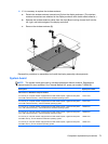
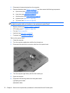
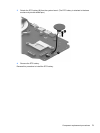
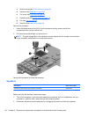
Remove the heat sink:
NOTE: Steps 1 and 2 apply to computer models equipped with a graphics subsystem with discrete
memory.
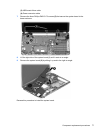
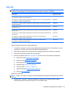
1. Following the 1 through 7 sequence stamped into the heat sink, loosen the seven captive
Phillips screws (1) that secure the heat sink to the system board.
Component replacement procedures 81