


3
1. INTRODUCTION
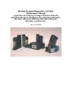
This document acts as a guide for the maintenance and care of Hewlett-Packard
disposable print cartidge products including the HP51626A, HP51638A,
HP51633M, HPC6117A, HP51640(A,C,M,Y), HP51641A, HPC6105A,
HPC1823A, HPC6116A, HP51645A, HPC6168A, HPC6169A, HPC6170A, and
HPC6104A. Each pen consists of a printhead and a pressurized ink source.
1.1 Background on Thermal Inkjet Technology
The disposable Hewlett-Packard cartridges are used in drop-on-demand thermal
inkjet systems. Inkjet systems fire small drops of ink to form text and images on
various types of medium.
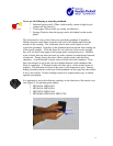
Thermal inkjet uses a firing resistor to vaporize a small amount of ink. The
vaporization process causes a small bubble to form. This bubble formation causes
a small drop of ink to be forced out of the firing chamber through the nozzle.
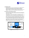
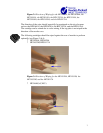
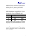
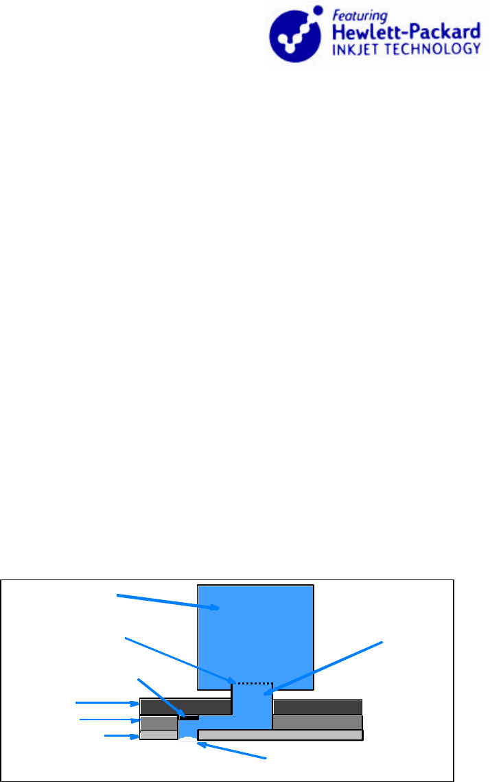
Figure 1 shows the major components of the thermal inkjet system. In the figure,
the entire ink supply is located near the printhead of the print cartridge. This is
the case for all of the Hewlett Packard disposable print cartridges. Back pressure
is controlled in the local ink supply by a spring or foam which prevents the ink
from seeping out of the nozzles. The filter screen keeps any large particles or air
bubbles away from the firing chambers. Bubbles or particles in the firing
chambers will prevent ink from coming out of the nozzle when the resistor heats
up. There is a firing resistor for every nozzle on the printhead.
Figure 1: Anatomy of a Printhead
Standpipe
Filter Screen
Firing
Resistor
Ink Supply
(Local or Bulk)
Nozzle
Ink Barrier
Substrate
Orifice
Surface
Section
of a
Printhead