


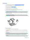

4. Apply the thermal grease provided in the spares kit to the top of the processor and install the
heat sink atop the processor.
5. Go to step 7.
6. If using a new heat sink, remove the protective covering from the bottom of the heat sink and
place it in position atop the processor.
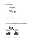
7. Secure the heat sink to the system board and system board tray with the four captive screws
and attach the heat sink control cable to the system board.
CAUTION: heat sink retaining screws should be tightened in diagonally opposite pairs (as in
an X) to evenly seat the heat sink on the processor. This is especially important as the pins on
the socket are very fragile and any damage to them may require replacing the system board.
NOTE: After installing a new processor onto the system board, always update the system ROM to
ensure that the latest version of the BIOS is being used on the computer. The latest system BIOS can
be found on the Web at:
http://h18000.www1.hp.com/support/files.
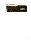
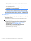
Power Supply
WARNING! To reduce potential safety issues, only the power supply provided with the computer, a
replacement power supply provided by HP, or a power supply purchased as an accessory from HP
should be used with the computer.
The rotating power supply is located at the rear of the chassis. It is held in place by a bracket – no
screws are used.
WARNING! Voltage is always present on the system board when the computer is plugged into an
active AC outlet. To avoid possible personal injury and damage to the equipment the power cord
should be disconnected from the computer and/or the AC outlet before opening the computer.
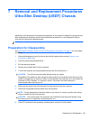
1. Prepare the computer for disassembly (Preparation for Disassembly on page 87).
2. Remove the access panel (
Computer Access Panel on page 95).
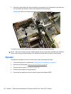
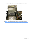
3. Rotate the drive cage up and disconnect the power cables from all of the drives.
4. Disconnect the power cables from the system board and drives.
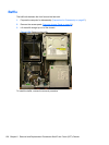
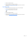
5. Rotate the power supply to its full upright position.
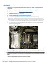
6. Release the power supply cables from the cable retaining clip under the drive cage.
136 Chapter 6 Removal and Replacement Procedures Small Form Factor (SFF) Chassis