


Index–6 Maintenance and Service Guide
Index
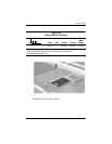
replacement
preliminaries
4–1
procedures
5–1
right-side components
1–16
RJ-11 telephone jack
location
1–16
pin assignments
A–2
RJ-45 network jack
location
1–17
pin assignments
A–1
RTC battery
illustrated
3–2, 3–8
removal
5–47
S
Screw Kit, spare part number
3–11, 3–15
scroll lock light, location
1–20
Secure Digital (SD) Card slot,
location
1–16
security cable slot, location
1–17
security module
removal
5–31
spare part number
3–11,
3–15, 5–31
serial connector
location
1–17
pin assignments
A–6
serial number
3–1, 5–2
service considerations
4–2
smart card
removal
5–19
spare part number
3–7,
3–16, 5–19
specifications
AC adapter
6–6
battery pack
6–6, 6–7, 6–8
CD-ROM drive
6–9
display
6–3, 6–4
DMA
6–12
DVD+RW/R and CD-RW
Combo drive
6–11
DVD/CD-RW combo drive
6–9
DVD-ROM drive
6–11
hard drive
6–5
I/O addresses
6–14
interrupts
6–13
notebook
6–1
static shielding materials
4–8
stereo speakers, location
1–15
S-Video connector
location
1–17
pin assignments
A–3
switch cover
illustrated
3–2
removal
5–28
spare part number
3–3,
5–28
system board
illustrated
3–6
removal
5–53
spare part numbers
3–7,
5–53
T
thermal grease, replacement
5–37
tools required
4–1
top components
1–20, 1–22