


6–38 Maintenance and Service Guide
Removal and Replacement Procedures
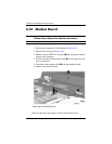
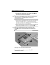
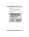
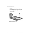
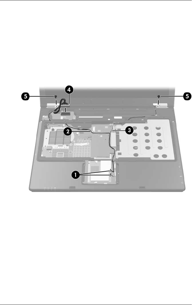
2. Disconnect the wireless antenna cables 1 from the Mini PCI
communications module.
3. Remove the wireless antenna cables from the Mini PCI
compartment and the top cover clips 2 and 3.
4. Disconnect the display cable 4 from the system board.
5. Remove the two PM2.0×4.0 screws 5 that secure the display
assembly to the computer.
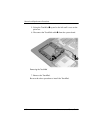
Disconnecting the Display Cable and Removing the Display Screws