


Removal and Replacement Procedures
Maintenance and Service Guide 6–53
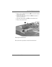
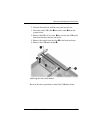
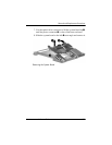
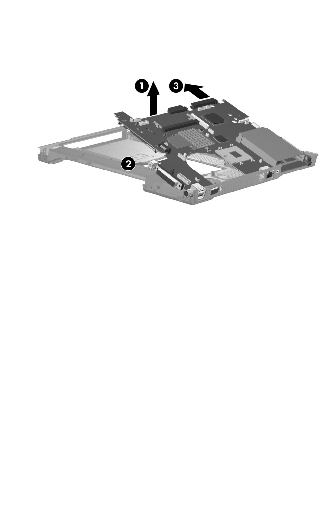
7. Use the optical drive connector to lift the system board up 1
until the power connector 2 is clear of the base enclosure.
8. Slide the system board to the left 3 at an angle and remove it.
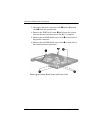
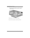
Removing the System Board