


5–50 Maintenance and Service Guide
Removal and Replacement Procedures
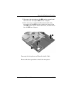
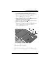
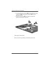
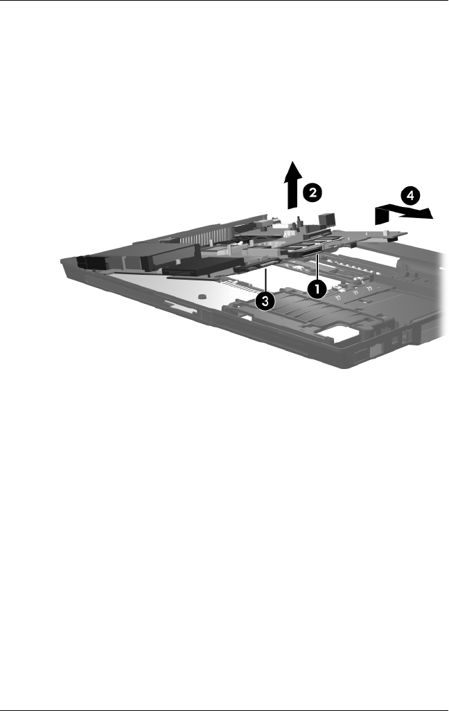
3. Use the optical drive connector 1 to lift the right side of the
system board 2 until the power connector 3 is clear of
the base enclosure.
4. Slide the system board 4 to the right at an angle and
remove it from the base enclosure.
Removing the System Board
Reverse the above procedures to install the system board.