


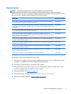

Fan/heat sink assembly
NOTE: The fan/heat sink assembly spare part kit includes replacement thermal material.
Replacement thermal material is also available in the Thermal Material Kit, spare part numbers
650277-001 (for use only with computer models equipped with an AMD processor) and 646135-001
(for use only with computer models equipped with an Intel processor).
Description Spare part number
For use only with computer models equipped with an AMD processor 647316-001
For use only with computer models equipped with an Intel Core i5 or i3 processor and a graphics
subsystem with discrete video memory
646182-001
For use only with computer models equipped with an Intel Core i5 or i3 processor and a graphics
subsystem with UMA video memory
646183-001
For use only with computer models equipped with an Intel Pentium processor and a graphics
subsystem with discrete video memory
646180-001
For use only with computer models equipped with an Intel Pentium processor and a graphics
subsystem with UMA video memory
646181-001
For use only with computer models equipped with an Intel Celeron processor and a graphics
subsystem with UMA video memory
646184-001
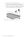
NOTE: To properly ventilate the computer, allow at least 7.6 cm (3 in) of clearance on the left side of
the computer. The computer uses an electric fan for ventilation. The fan is controlled by a temperature
sensor and is designed to turn on automatically when high temperature conditions exist. These
conditions are affected by high external temperatures, system power consumption, power
management/battery conservation configurations, battery fast charging, and software requirements.
Exhaust air is displaced through the ventilation grill located on the left side of the computer.
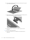
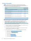
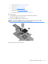
Before removing the fan/heat sink assembly, follow these steps:
1.
Shut down the computer. If you are unsure whether the computer is off or in Hibernation, turn the
computer on, and then shut it down through the operating system.
2. Disconnect all external devices connected to the computer.
3.
Disconnect the power from the computer by first unplugging the power cord from the AC outlet
and then unplugging the AC adapter from the computer.
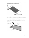
4. Remove the battery (see
Battery on page 39), and then remove the following components:
●
Optical drive (see
Optical drive (select models only) on page 40)
●
WLAN module (see
WLAN module on page 43)
●
Keyboard (see
Keyboard on page 49)
●
Top cover (see
Top cover on page 52)
●
USB board (see
USB board on page 59)
●
Power connector cable (see
Power connector cable on page 60)
76 Chapter 4 Removal and replacement procedures