


RPC SERIES OWNER’S MANUAL
CABLING
________________________________________________________________________________
16
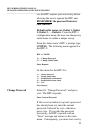
The RPC RJ-45 control port uses the following signals:
EIA-232 RJ-45 PIN/SIGNAL DEFINITION
Pin
EIA-232
Signal
Direction Description
1DTR Output
+10V when activated by DCD. Toggles on logout for modem disconnect.
2 GND ---- Signal Ground
3RTS Output
+10V when powered is applied, not used as a handshake line
4 TX Output Transmit Data (data out)
5 RX Input Receive Data (data in)
6 N/C N/C No Connection
7 GND -------
Signal Ground
8 DCD Input
DCD into the RPC/Not used on RPC-2 MD01
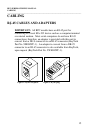
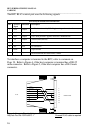
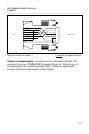
To interface a computer or terminal to the RPC, refer to comment on
Page 19. Refer to Figure 4, if the host computer or terminal has a DB-25
male connector. Refer to Figure 5, if the host computer has a DE-9 male
connector.
1
2
3
4
5
6
7
8
20
8
7
6
5
4
3
2
RTS
RX
DCD
DTR
GND
DSR
TX
CTS
FEMALE DB-25
RJ-45
BLUE
ORANGE
BLACK
RED
GREEN
YELLOW
BROWN
GRAY
Figure 4: Computer/Terminal Adapter
BayTech Part No. 25FRJ45PC-1 Crossed RJ-45 cable is required