


4. Enter the tsclockserver command to
synchronize local time using NTP:
switch:admin> tsclockserver
“<ntp1;ntp2>”
The value of ntp1 is the IP address or DNS name
of the first NTP server, which the switch must be
able to access. The value of ntp2 is the second
NTP server and is optional. When multiple NTP
server addresses are specified, tsclockserver
sets the first obtainable address as the active NTP
server. The default value is LOCL.
switch:admin> tsclockserver
LOCL
switch:admin> tsclockserver "132.163.135.131"
switch:admin> tsclockserver
132.163.135.131
switch:admin>
Configure the zones, and perform device selection
See the Brocade Network Advisor User Manual,
available from the storage section of the HP website:
http://www.hp.com/support/manuals.
Connect devices
The Connect Devices window shows a graphical
representation of the switch with the device
connections, based on the information that you entered
in “Configure the zones, and perform device selection”
(page 7).
NOTE: Only HP B-series optical transceivers
are supported. See http://hpsancompat.com/
for more information.
To connect devices:
Transceivers and cables are keyed so that they can
be inserted only one way. If a transceiver or cable
does not slide in easily, make sure it is oriented
correctly.
Do not insert a cable intended for an mSFP transceiver
into a regular SFP+ transceiver; you may damage the
cable. The mSFP transceivers and cables are supported
only with the 64-port 8Gb/s blade for the SN8000B
SAN directors. Do not force a standard SFP cable into
an mSFP transceiver; you may damage the transceiver.
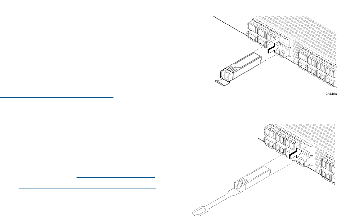
1. Install the SFP+ transceivers in the Fibre Channel
ports on the switch to match the ports shown on
the screen (see Figure 8 (page 7)). If you are
using an SFP+ transceiver that does not have a
pull tab, ensure that the wire bail is in the
unlocked position.
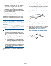
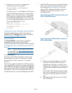
Figure 8 Inserting an SFP+ transceiver with no pull
tab in a Fibre Channel port
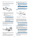
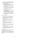
Figure 9 Inserting a 16 Gb/s SFP+ transceiver in
a Fibre Channel port
a. Remove any protector plugs from the SFP+
transceiver. Insert each SFP+ transceiver
(right side up in the top row of ports, and
upside down in the bottom row of ports) until
it is firmly seated and the latching mechanism
clicks.
The 16 Gb/s SFP+ transceivers do not have
bails. Use the pull tab on the 16 Gb/s SFP+
transceiver to push the transceiver into the
port.
b. Close the latching bail on the non-16 Gb/s
SFP+ transceiver.
Page 7