


5–32 Maintenance and Service Guide
Removal and Replacement Procedures
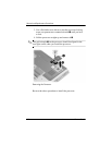
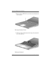
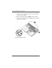
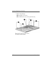
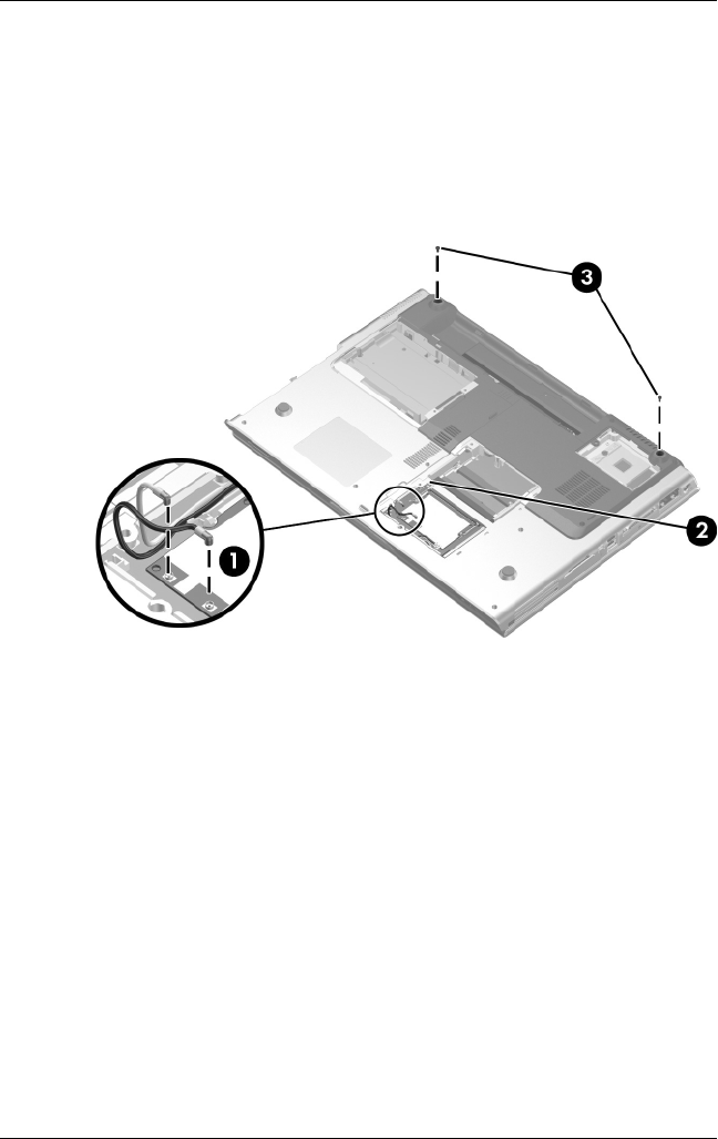
5. Disconnect the wireless antenna cables from the Mini PCI
communications card 1.
6. Remove the cables from the clip 2 in the base enclosure.
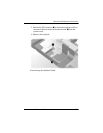
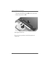
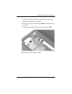
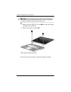
7. Remove the two PM2.5×7.0 screws 3 that secure the display
assembly to the notebook.
Removing the Display Screws