


HP Wireless LAN Assessment Report
HP Internal Use Only Page 8
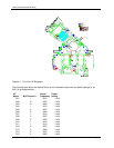
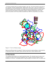
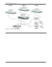
The following drawings show the predicted coverage for each floor. The Circles indicate the antennas are
omni directional. The color indicates the 802.11 B/G channel number. Red is 1, Blue is 6, and Green is 11.
The shapes around the antennas predict the coverage area for that specific access point. Circles or shapes
without a transmitter name in the center, are wireless coverage from access points on a different floor.
These are shown to help assign the frequencies in order to not allow overlap between floors. These
pictures are available, and will be provided as AutoCAD files or WMF files, as specified by the customer.
Lounge
270
3113
Air Classic
Pro
3109
Air
Birkdale
3110
Course Air
Tour
3116
Elite Feel
3115
T W - 3
Contr ol Ro om
3132
3121 3123 3125
3126
Diagram 2 – First floor Wireless coverage
Cabling to the AP should be to the closest IDF. Switch ports should be made available on existing switches,
or new switches added. Inline power injectors should be used there to reduce installation costs.
3.2 Site Details
This installation should create a very large flat switched network. This will make it easy for users to roam
throughout the center without having to renegotiate a new IP address. Care should be taken to keep
broadcasts to a minimum. If broadcasts become a large percentage of the network traffic, the network may