


Chapter 2
Page 6 of 16
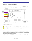
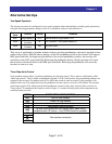
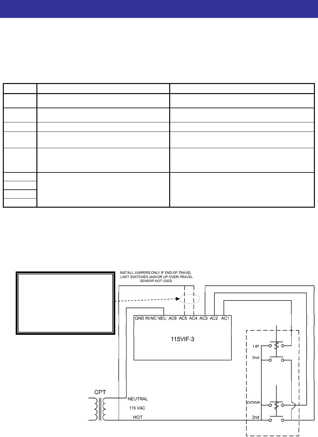
AC Input Wiring – Connecting the Pendant to the 115VIF-3 Interface Board
Connect the pendant 115 VAC input wiring to the terminals marked AC1 through AC5 on the 115VIF-3, with
NEU (neutral of the pendant control signals) as their common terminal. AC1 thru AC5 are connected to the
HOT side of the pendant control signals, coming from the pendant’s pushbutton contacts. The board’s AC input
terminal functions are as follows:
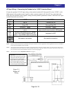
INPUT HOIST TRAVERSE
AC1
(Note 1)
Up PB Forward/Left PB
AC2
(Note 1)
Down PB Reverse/Right PB
AC3
Increase/2
nd
speed Increase/2
nd
speed
AC4
(Note 2)
Jumpered to HOT
(Note 3)
Horizontal over-travel limit (NC sensor input;
open-circuit forces inverter to MIN speed)
AC5
(Note 2)
Up over-travel photo limit (NC sensor
input; open-circuit stops/prevents UP
motion – only DOWN motion is possible)
Jumpered to HOT
AC6
NC
IN
GND
Not used/no connection Not used/no connection
Note 1: Inputs AC1 and AC2 functions are symmetrical with respect to direction in traverse applications. In hoist applications, however, AC1 must be
used for UP and AC2 must be used for DOWN.
Note 2: AC4 and AC5 inputs are intended to be used with over-travel limit sensors. These are secondary safeties, over and above N.C. limit switches
that would be wired in series with the AC1 and AC2 pendant inputs. They are “fail-safe” inputs, for use with N.C. type sensors. In this way, a
cut wire will have the same effect (inhibited of motion) as a sensor being triggered.
Note 3: AC4 may also be used for 3-Step Hoist Control. Refer to page 11.
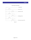
Figure 2-2,
Pendant AC
Wiring
Important: If you will not use the
AC4 or AC5 for end-of-travel safety
inputs, then both these inputs must
be jumpered to the pendant HOT
supply, otherwise motor rotation will
be prevented. When end of travel
limit switches ARE used, they should
be wired in place of these jumpers.
PENDANT