


APPD
CHKD
DSGN
DWN
Hitachi Kokusai Electric Inc
Tokyo Japan
・ ・
・ ・
・・
・・
1
2
3
4
A
B
C
D
E
F
1
2
3
HV-D27A/HV-D37A
Color Camera
Tentative
Specification
(
7/17
)
5. Input and output signals
5-1. Input signal conditions
1) Genlock input (MULTI connector)
・
VBS 1.0 Vp-p
±
3 dB or black burst/75
Ω
or high (BNC)
(sync 0.3
±
0.1 Vp-p, burst 0.3
±
0.1 Vp-p)
・
HD/VD 2 to 5 Vp-p, negative (D-sub connector)
Note: Genlock input and Sync output are selected by internal input/output switch.
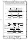
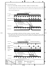
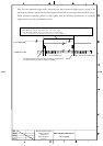
2) External trigger input (MULTI connector)
Ext Trig Low 0 VDC, High 2 to 5 VDC
3) Serial data (REMOTE connector)
1.5 Vp-p
±
3 dB/High (when connected to RC-Z3, JU-C20, JU-Z2)
RS-232C level (when connected to personal computer)
Note: Set internal switches according to connected equipment.)
A level converter JU-C20 is required if controlling the camera from a personal computer via
RS-232C interface over a distance more than approx.15 meter.
5-2. Output signal ratings
1) Component video output (VIDEO, MULTI connector)
VBS 1.0 Vp-p/75Ω
2) Y/C output (Y/C connector, MULTI connector)
Y: 1.0 Vp-p/75
Ω
C: NTSC 0.286 Vp-p (burst)/75
Ω
PAL 0.3 Vp-p (burst)/75
Ω
3) Component output (MULTI connector)
Y: 1.0 Vp-p/75
Ω
R-Y/B-Y: 0.7 Vp-p/75
Ω
4) RGB output (MULTI connector)
RGB: 0.7 Vp-p/75
Ω
Note: YC/VBS, component and RGB MULTI connector outputs are selected by menu.
5) Sync outputs (MULTI connector)
HD/VD: 2 Vp-p/75
Ω
Sync: 2 Vp-p/75
Ω
Note: Genlock input and Sync output are selected by internal input/output switch.
6) Serial data output (REMOTE connector)
1.5 Vp-p/Low (when connected to RC-Z3, JU-C2-, JU-Z2)
RS-232C level (when connected to personal computer)
Note: Set internal switches according to connected equipment.)