10/10/03
CHAPTER 9 HP-GL - 18
3.5. Plot Function Instructions
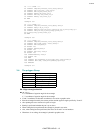
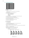
Instruction Function
FT Fill Type
LT Line Type
PW Pen Width
SM Symbol Mode
SP Select Pen
TL Tick Length
XT X Tick
YT Y Tick
PT Pen Thickness
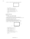
FT - Fill type
FT [ n [, d [, q]]] [;]
n : Fill type
d : Fill interval (interval between the parallel lines of the area being filled)
q : Fill angle (degrees )
• Sets the fill type, interval and angle when filling an area.
• The value for n is a clamped integer number.
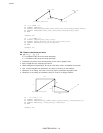
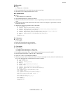
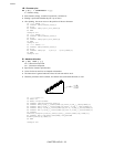
Solid lines (bi-directional fill)
Solid lines (single direction fill)
Parallel lines
Crosshatching
• The fill interval when n is 1 or 2 is the interval set by the pen thickness (PT) instruction.
• Any value given for d when n is 1 or 2 will be ignored.
• If d is omitted, the fill interval already specified will be used.
•
If d is 0, the default value will be used ( 1% of distance from P1 to P2. )
• The value of d is a clamped real number .
• If q is omitted, the fill angle already specified will be used.
• The value of q is a clamped real number.
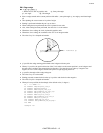
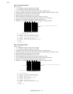
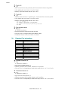
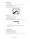
LT - Line type selection
LT [, n [, p ]] [;]
n ; Line pattern number
p ; Line pattern length (percentage or millimeters of distance between P1 and P2)
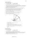
•
Specifies the line type and pattern length.
• When the n parameter field is omitted a solid line is selected.
• When the p parameter field is omitted the pattern length is 4% of the distance between P1 and P2 (default
value ).
• The value of n is a clamped integer number.
• The value of p is a clamped real number from 0.0000 to 127.9999.
• When p is omitted the previously set line pattern length is used.
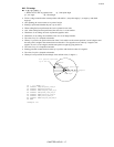
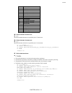
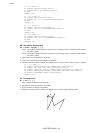
Default :Solid line
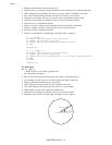
:For straight line, start and end points are plotted.
:For an arc, plotting takes place for every chord angle that is set.
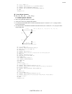
1 :
2 :
3 :
4 :
5 :
6 :
P


