


7800 SERIES S7810B MULTI-DROP SWITCH MODULE
3 65-0228—3
Canadian EMI: This digital apparatus does not exceed the
Class A limits for radio noise emission from digital apparatus
set out in the Radio Interference Regulations of the Canadian
Department of Communications.
Le présent appareil numérique n’émet pas de bruits
radioélectriques dépassant les limites applicables aux
appareils numériques de la Classe A prescrites dans le
Règlement sur le brouillage radioeléctrique édicté par le
ministère des Communications du Canada.
Humidity
Install the S7810B where the relative humidity never reaches
the saturation point. The S7810B is designed to operate in a
maximum humidity environment of 85 percent relative humidity
continuous, noncondensing moisture.
Weather
The S7810B is not designed to be weather-tight. When
installed outdoors, protect the S7810B with an approved
weather-tight enclosure.
Vibration
Do not install the S7810B where it could be subjected to
vibration in excess of 0.5G continuous maximum vibration.
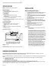
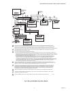
Mounting the S7810B Multi-Drop Switch
Module.
1. Align the two ears of the Multi-Drop Switch Module with
the two mating slots on the 7800 SERIES Relay Module.
2. Insert the two interlocking ears into the two mating slots
and, with a hinge action, push on the lower corners of
the Multi-Drop Switch Module to secure it to the 7800
SERIES Relay Module.
Wiring (Fig. 2)
1. Refer to Fig. 2 for proper wiring.
2. All wiring must comply with all applicable electrical
codes, ordinances and regulations.
3. Recommended wiring size and type:
a. For ControlBus™ communications, use 22 AWG,
3-wire shielded cable (Belden part number 8723 or
equivalent).
b. For 13 Vdc and remote reset switch operation, use
22 AWG wire insulated for voltages and
temperatures in the application. Suggested wire
types include TW (60°C), THW (75°C) and THHN
(90°C) Terminal identification numbers and letters
shown in Table 1.
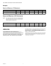
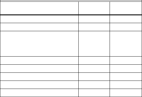
Table 1. S7810B and QS7800B Terminal Identification.
4. Wire routing:
a. Do not route the ControlBusª cable in conduit with
line voltage circuits.
b. Do not route the ControlBusª cable close to the
ignition transformers.
c. Route the ControlBusª cable outside of conduit if
properly supported and protected from damage.
d. Route the ControlBusª cable so that all devices are
connected in a daisy chain configuration. See Fig. 3.
5. Maximum wire lengths:
a. RS-485 Communications bus, 4000 feet
(1219 meters).
b. Remote reset switch, 1000 feet (305 meters).
BUILDING A MULTI-DROP NETWORK
The subnetwork addressing in the Q7700 Network Interface
Unit (NIU) is not contiguous. It is divided into two blocks,
containing 198 and 24 addresses, respectively. A maximum
multi-drop configuration would include 222 subnetworks
(198 plus 24) on a single Q7700 NIU.
One QS7800B ControlBusª Module card supports up to 31
multi-drop subnetworks without using an RS-485 repeater. If
an RS-485 repeater is used, up to 61 multi-drop subnetworks
can be supported by one QS7800B card. The RS-485 repeater
must be installed between the 30th and 31st subnetworks.
Each subnetwork includes one 7800 SERIES controller with or
without an S7800 Keyboard Display Module and/or an S7830
Expanded Annunciator. An S7810B1007 Multi-Drop Switch
Module is required in each subnetwork. See Fig. 3 for wiring
information.
Subnetworks can be spread evenly (balanced) across the NIU
slots to improve speed of communications.
It is recommended that the multi-drop network be built starting
with slot number 1 of the NIU, subject to the above guidelines.
Record the serial number and physical location of each
S7810B Multi-Drop Switch. This data will be useful when
commissioning the ZM7850 Combustion System Manager
(CSM) software. Refer to CSM manual, form 65-0102, for CSM
commissioning.
Signal
S7810B
Terminal
QS7800B
Terminal
Local Bus Data + 1 None
Local Bus Data - 2 None
Common
• Local Bus Common
• +13 Vdc Common
• Remote Reset Common
3 None
+13 Vdc 4 None
Remote Reset 5 None
Multi-Drop Bus Common 6 c
Multi-Drop Bus Data + 7 a
Multi-Drop Bus Data - 8 b