


LONWORKS® BUS WIRING GUIDELINES
74-2865—04 2
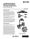
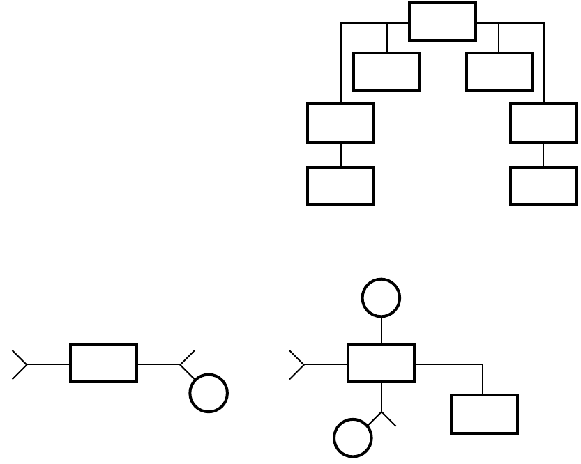
System expansion is simplified by the use of physical layer
repeaters and routers. The Q7740A 2-Way or Q7740B 4-Way
devices perform a repeater function, and the Q7751A
operates as a router. See Fig. 2. If a L
ONWORKS Bus segment
grows beyond the maximum number of devices or total wire
distance, additional FTT segments can be added. This is done
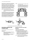
by connecting a Q7740A 2-Way or a Q7740B 4-Way physical
layer repeater (see Fig. 3). The repeaters will transfer data
between the two L
ONWORKS Bus segments, allowing the
number of devices to be spread out as well as increasing the
length of wire over which they communicate.
NOTE: Do not exceed the maximum of 120 devices for a
Q7750A Zone Managers L
ONWORKS Bus network
(up to 60 devices are allowed per L
ONWORKS Bus
segment).
The repeater function permits an FTT network to grow as
system needs expand, without retrofitting existing controllers
or requiring the use of specialized bridges. The maximum
number of repeaters per L
ONWORKS Bus segment is one
(on either side of the router). A Q7751A L
ONWORKS Bus
router can also be used to effectively double the maximum
L
ONWORKS Bus length. The advantage of using the router is
that it will segregate traffic to a L
ONWORKS Bus segment.
When using the repeater all traffic is repeated on each
L
ONWORKS Bus segment. (see following NOTES).
NOTES:
— There can be no more than one repeater on either
side of a Q7751A router.
— An FTT network can have no more than one router
per Zone Manager. Systems requiring high levels
of network traffic may benefit from the use of a
Q7751A router, which forwards packets only when
necessary. Routers are not allowed within loops.
Fig. 2. Repeaters and router in a FTT network.
Fig. 3. Physical layer repeater (Q7740A 2-Way or Q7750B 4-Way).
NETWORK CABLING AND
CONNECTIONS
This section provides information about cabling and FTT
network connections.
IMPORTANT
• For network terminal connections, twist the wires
together a minimum of three times.
• Only use approved wire and do not use different wire
types on the same bus.
• Follow the bus length limits for the cable type used.
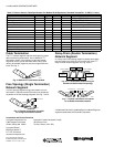
• Properly install the 209541B FTT Termination
Module, see Fig. 4 through 7.
System Performance and Cable
Selection
Transmission Specifications
The free topology transmission specifications include two
rules that must both be met for proper system operation:
1. The distance from each device to all other devices and
to the termination must not exceed the (singly
terminated) maximum node-to-node (device-to-device)
distance. For example, if multiple paths exist using loop
topology, then use the longest path for the calculations.
2. The maximum total wire length is the total amount of
wire connected per L
ONWORKS Bus segment.
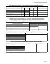
NOTE: See Table 1 for daisy-chain doubly terminated FTT
network bus topology transmission specifications
and Echelon® cable parameters.
209541B
TERMINATION
MODULE
209541B
TERMINATION
MODULE
209541B
TERMINATION
MODULE
Q7740A
REPEATER
Q7740A
REPEATER
Q7751A2002
ROUTER
DAISY-CHAIN
TOPOLOGY
DAISY-CHAIN
TOPOLOGY
DAISY-CHAIN
TOPOLOGY
DAISY-CHAIN
TOPOLOGY
209541B
TERMINATION
MODULE
M12369A
Q7740B
4-WAY
REPEATER
209541B
TERMINATION
MODULE
DAISY-CHAIN
TOPOLOGY
FREE
TOPOLOGY
FREE
TOPOLOGY
FREE
TOPOLOGY
M12368
Q7740A
2-WAY
REPEATER
FREE
TOPOLOGY
FREE
TOPOLOGY