


C6097A,B PRESSURE SWITCHES
65-0237—1 4
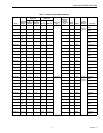
Table 2. Switch Ratings (Amperes)
Table 3. Alternate Electrical Ratings when used with
Honeywell Flame Safeguard Programmers.
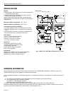
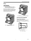
Fig. 2. C6097 Flange Mount dimensions in in. (mm).
INSTALLATION
WARNING
Explosion or Fire Hazard.
Can cause severe personal injury, death or
property damage.
Observe all safety requirements each time a control is
installed on a burner.
When Installing this Product...
1.
Read these instructions carefully. Failure to follow them
can damage the product or cause a hazardous
condition.
2.
Check the ratings given in the instructions and on the
product to make sure that the product is suitable for
your application.
3.
Installer must be a trained, experienced service
technician.
4.
After installation is completed, check out product
operation as provided in these instructions.
WARNING
Electrical Shock Hazard.
Can cause serious personal injury or death.
Disconnect power supply before beginning installation.
More than one disconnection can be involved.
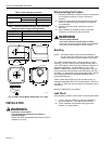
Mounting
NOTE: On flange models, remove the label holding the
O-ring in place and make sure O-ring seal is in place
before mounting the pressure switch on the valve.
The C6097 models allow NPT or flange (directly to valve)
mounting. The NPT models have a hexagonal fitting with a
1/4 in. NPT tapping, which is the high pressure connection, in
differential applications. The bleed fitting is 1/8 in. NPT
tapped. In differential pressure control applications using air
only, connect the lower pressure to the bleed fitting. See Fig. 1
and Table 1. In applications using combustible gases, vent the
bleed tapping according to applicable standard code or
jurisdictional authority.
C6097 models with flange mount can be fitted directly to
Honeywell Integrated Valve Train (model specific). See Fig. 2
and Table 1. The flange mount models vent internally, with no
external tap.
Mount the C6097A,B in any position.
Leak Check
After installation, perform a leak check on the pressure switch:
1.
Turn on main gas. Make sure gas has reached the
pressure switch (e.g., high gas pressure switch)
2.
Check installation for gas leaks using a gas leak
detector or a soap solution.
120/240 Vac, 50/60 Hz
Inductive Full Load 3.0
Locked Rotor 18.0
Resistive 5.0
Device Rating
Ignition Transformer 540 VA
Pilot Valve 50 VA
Main Valve 400 VA with 2-1/2 times inrush.
27/32 (22) HOLE
PRESSURE INLET
5/8 (16)
2-1/4
(57)
2
(52)
2 (52)
1-1/4
(32)
1/32
(1)
2-21/32 (68)
2-23/32 (69)
2-23/32 (69)
INDICATOR
M17124
12 3
P
NO
NC
COM
TERMINAL DIAGRAM