


SOLID CORE AND SPLIT CORE ADJUSTABLE CURRENT “STATUS” SWITCHES
62-0242—01 2
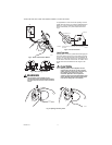
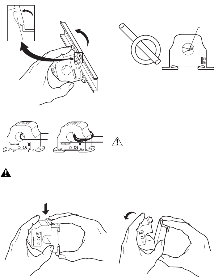
Fig. 2. Sensor removed from DIN rail
Fig. 3. Wires through sensors
WARNING
The secondary of the 5 Amps Current
Transformer must be shorted together before
the power may be turned on to the monitored
device.
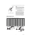
For applications in which the normal operating current is
greater than 250 Amps or for conductor diameters larger
that 3/4 in. (19 mm) in diameter, and external 5 Amps
Current Transformer (C.T.) must be used as shown in
Fig. 4.
Fig. 4. Current transformer
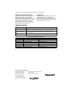
Latch Operation
Pressing down on the two (2) side tabs and swinging the
cover open opens the split core current switch as shown
in Fig. 5. Lifting up the latch with a flat-tip screwdriver as
shown in Fig. 6 can also open the unit. Press down firmly
on the cover to close the current switch. An audible “click”
will be heard as the tab slides over the tongue on the
base.
CAUTION
Mating surfaces of the magnetic core are
exposed when the sensor is open. Silicone
grease, present on the cores to prevent rust,
can capture grit and dirt if care is not
exercised. Operation can be impaired if
anything prevents good contact between pole
pieces. Visually check the mating parts of the
core before closing the current sensor.
Fig. 5. Opening sensor by hand
3X
M25290
C
R
U
L
U
S
M25291
U
R
C
L
US
U
R
C
L
US
EXAMPLE: FOR CURRENTS UP TO 600 AMPS, USE A 600:5 RATIO C.T.
AS SHOWN.
INSULATED CONDUCTOR
600:5 RATIO 5A C.T.
WIRE NUT
M25295A
C
U
R
L
US
C
US
R
U
L
M25298