


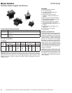

Manual Switches NT/NR Series
Flat Base Sealed Toggles and Rockers
126HoneywellɀSensingandControlɀ1-800-537-6945USAɀ⍣1-815-235-6847Internationalɀ1-800-737-3360Canada
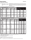
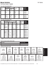
UL AND CSA ELECTRICAL RATINGS
Rating Code* Electrical Rating
L192 10 amps, 125, 250, 277 VAC;
1
⁄4 Hp, 125 VAC;
1
⁄2 Hp, 250, 277 VAC; 3 amps,
125 VAC
‘‘
L’’
L191 15 amps, 125, 250, 277 VAC;
1
⁄2 Hp, 125 VAC; 1 Hp, 250, 277 VAC; 5 amps,
125 VAC
‘‘
L’’
ELECTRICAL RATINGS
In Amperes
115 Volts AC
28 Volts DC 115 VDC 250 VDC 60 & 400 Hz 230 VAC
Rating
Code Ind. Res. Lamp Res. Res. Ind. Res. Lamp Res.
1 12 20 5 0.75 0.5 10 15 3 6
2 10 15 4 0.75 0.5 7 15 2 6
3 15 20 7 0.75 0.5 15 15 4 6
4 10 18 5 0.75 0.5 8 11 2 6
Application Note: Honeywell MICRO SWITCH does
not
recommend the use of silver
cadmium oxide switch contacts in non-arcing loads. Non-arcing loads are generally
loads less than 12 volts and/or 0.5 amp. NT/NR switches use silver cadmium oxide
contacts. For other options, contact the MICRO SWITCH Application Center at
1-800-537-6945.
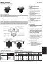
FEATURES
ɀ Sealed switching chamber
ɀ 1 or 2-pole circuitry
ɀ 2 or 3 position maintained and
momentary action
ɀ Flat base with quick-connect
terminals – mating connectors are
available
ɀ Brightly colored removable rockers
ɀ Spring-loaded actuating mechanism
provides tactile feedback
ɀ High impact strength, non-tracking
case enhances electrical stability
ɀ Temperature range: –40 to 71°C (–40
to 160°F)
ɀ UL Recognized, File E12252, vol. 1,
section 44
ɀ CSA Certified, File LR4442
ɀ CE approved
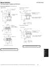
GENERAL INFORMATION
MICRO SWITCH NT Seriestoggle switch-
es and NR Series rocker switches are
designed to meetsevere environment ap-
plication needs for rugged, cost-effective
manual switches. These flat base style
products are identical to the stepped
base style in construction and features.
The flat base allows for PC board or con-
nector use for easy wiring/connection.
The flat base NT toggle switches and NR
rocker switches are provided with quick-
connect (spade) termination. Mating con-
nectors are available.
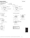
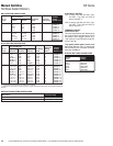
TERMINAL CIRCUIT IDENTIFICATION
Terminal identifications are referenced in
the order guides to indicate which circuits
are made in each toggle position (e.g.
‘‘1-2’’ refers to circuit closure through ter-
minals 1 and 2).