


Q7130A, Q7230A, Q7330A MODUTROL IV INTERFACE MODULES
63-2235—05 4
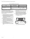
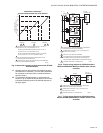
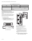
Q7230 Adjustments (Fig. 4 and Table 3)
The Q7230A provides adjustable range (zero and span) for
two-wire current or voltage control. Separate potentiometers
are provided on the circuit module for adjusting the zero point
and the span. It includes a cw/ccw switch for configuring the
motor to rotate clockwise or counterclockwise with an
increase in control signal.
1. Verify that the zero potentiometer is fully clockwise and
that the span potentiometer is fully counterclockwise.
2. Select desired rotation direction [cw (electrically nor-
mally closed) is the most common]. The following direc-
tions apply for the clockwise setting. For
counterclockwise setting, reverse open and closed, and
reverse clockwise and counterclockwise. Remove film
on switch before use.
3. See Fig. 6 and 7 for typical system wiring.
4. For current control, connect the current input signal to I+
(screw terminal 3) and COM (screw terminal 5). For
voltage control, connect the voltage input signal to V+
(screw terminal 1) and COM (screw terminal 5).
5. Set the controller to output the signal required to drive
the motor to the closed position. Wait for the motor to
stop driving closed.
6. Turn the zero potentiometer slowly counterclockwise
until the motor starts to open.
7. Turn the zero potentiometer slowly clockwise
until the motor is fully closed. This is defined as the zero
setting.
8. Set the controller to output the signal required to drive
the motor to the fully open position. Wait for the motor to
stop driving open.
9. Turn the span potentiometer slowly clockwise
until the motor starts to drive closed. The difference
between the fully open position signal and the fully
closed position signal is defined as the operating span.
10. Recheck the fully closed position and readjust the zero
potentiometer, if necessary. (Turn the zero potentiome-
ter clockwise to close the motor and counter-
clockwise to open the motor.)
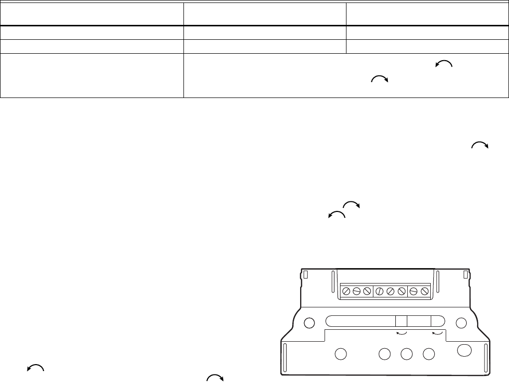
Fig. 4. Q7230A terminals and adjustments.
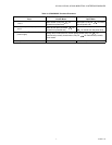
Table 2. Q7130A/M91XX Checkout Procedure.
Step
Proper Motor Response Switch in
Clockwise Position Switch in Counterclockwise Position
1. Open terminal C or R. Motor runs closed (fully ccw). Motor runs open (fully cw).
2. Jumper terminals C and F. Motor runs fully open (fully cw). Motor runs fully closed (fully ccw).
3. Remove either T terminal or disconnect
power supply.
Spring return motors return to normal spring position (fully ccw for
mechanically normally closed motors; fully cw for mechanically normally
open motors).
M27213
T1
T2
F
Com
V+
CCW
CW
ZEROSPAN
1+