1 69-0791—3J.H. • Rev. 10-94 • ©Honeywell Inc. 1994 • Form Number 69-0791—3
R182J, R482J, R845A,
R847A, RA89A, RA832A
Switching Relays
Application
These relays can be used for a variety of switching applications. Typically they provide control of line- or low-voltage
devices by a low voltage controller. See Table 1.
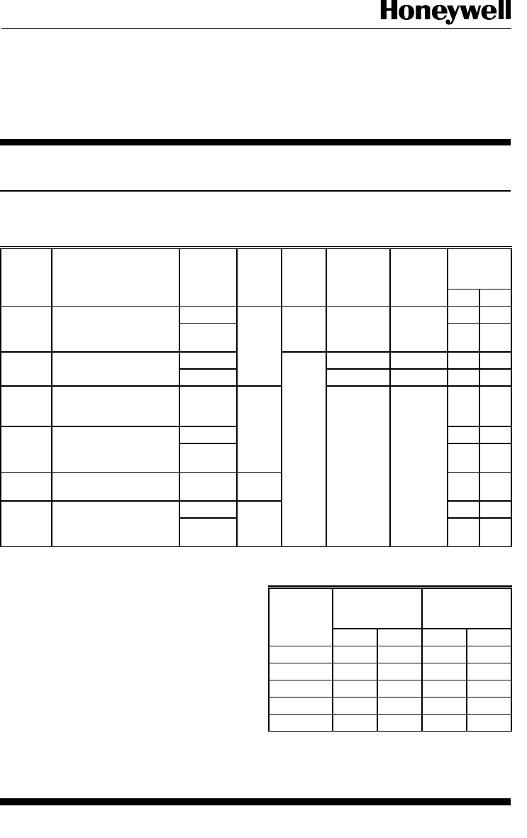
TABLE 1—SWITCHING RELAY SPECIFICATIONS.
TRADELINE
®
Voltage Switch Control
Coil
Voltage
(Vac at
Relay Coil
Current
Contact
Ratings (A)
Models Application
(50/60 Hz) Action Circuit 50/60 Hz) (A)
AFL ALR
R182J
For 24V thermostat
120 Dpdt 3-wire 24 0.40
a
7.4 44.4
control of line voltage
devices.
240 3.7 22.2
R482J
Controlled by a line
120 2-wire 120 0.08 7.4 44.4
voltage controller
208/240 208/240 0.04 3.7 22.2
R845A For hot water zone control
systems or spst control of
two separate loads.
120 Dpst 24 0.40 7.4 44.4
R847A
Provides switching for
120 22 100
high-current loads such as
cooling compressors.
240 10 50
RA89A For switching one line
voltage load.
120 Spst 10.2 61.2
RA832A
For switching two line
120 Dpst 7.4 44.4
voltage loads with a
common power source.
240 3.7 22.2
a
IMPORTANT: The transformer on the R182 can over-
heat when used with a series 20 thermostat if the
total resistance of the thermostat circuit exceeds
2.5 ohms. If the measured resistance of the thermo-
stat (including thermostat wire and thermostat con-
tact resistance) exceeds 2.5 ohms, add a 100 ohm,
10 watt resistor between the W and R terminals.
Table 2 gives maximum thermostat wire runs; if
longer runs are necessary, measure the resistance or
add a 100 ohm, 10 watt resistor across terminals W
and R.
TABLE 2—LENGTH OF WIRE.
AWG
Wire
Size
Total Wire
Length
Length of Run
to Thermostat
(Wires)
(Number)
Feet Meters Feet Meters
22 120 38.0 60 18.0
20 200 61.0 100 30.5
18 300 91.5 150 45.5
16 500 152.5 250 76.0
14 800 244.0 400 122.0


