


69-0791—32
Installation
WHEN INSTALLING THIS PRODUCT…
1. Read these instructions carefully. Failure to follow
instructions can damage product or cause a hazardous
condition.
2. Check the ratings given in the instructions and on the
product to make sure the product is suitable for your
application.
3. Make sure installer is a trained, experienced service
technician.
4. After completing installation, use these instructions
to check out product operation.
WARNING
ELECTROCUTION HAZARD CAN
CAUSE PROPERTY DAMAGE, SEVERE
INJURY, OR DEATH.
Transformer core not bonded.
Disconnect power supply before wiring to pre-
vent electrical shock or equipment damage.
MOUNTING
For replacement, mount the relay in the same location as
the old relay. If this is a new installation, locate the relay
vertically on a solid wall or partition as close as possible to
the device to be controlled. Select a location that is easily
accessible for installation and service.
NOTE: To reduce the possible transformer hum and relay
noise that is sometimes amplified by mounting surfaces
such as sheetmetal, plasterboard, and similar materials,
place rubber or felt washers between the case and the
mounting surface.
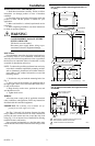
1. Position the relay and mark the mounting holes. See
Fig. 1.
2. Start a screw for the keyhole type mounting hole in
the upper right corner. Screw it down within about 1/8 in.
[3 mm] of the surface.
3. Hang the relay on the screw, position the case, and
start the bottom screw.
4. Tighten both screws.
WIRING
All wiring must comply with all applicable electrical
codes, ordinances, and regulations. Follow any instructions
furnished with the controlled equipment.
IMPORTANT: The switching relay terminals are ap-
proved for use with copper wires only.
See Figs. 2 through 9 for hookup diagrams for these
relays. When two or more devices are to be controlled in
parallel, the total current must not exceed the relay load
rating. Fig. 11 is an internal view of the RA832A showing
terminal locations and barriers.
Never connect load terminals to a load that takes more
current than the amount listed in the electrical ratings on the
relay.
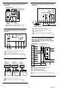
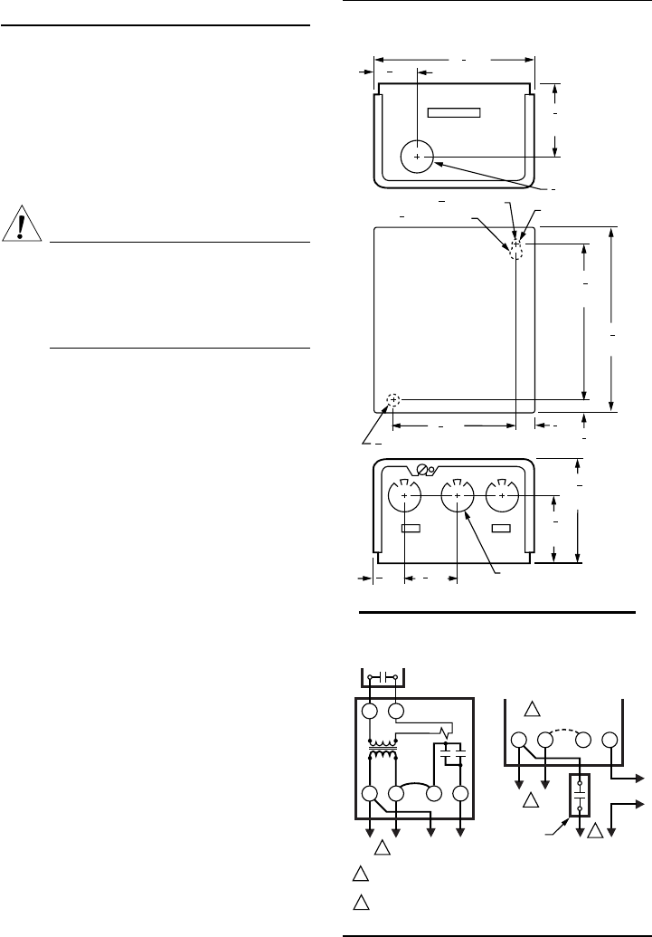
Fig. 1—Approximate mounting dimensions in
in. [mm].
4
[114]
1
2
1
[48]
7
8
3
8
[10]
3
8
[10]
5
32
1 [29]
1
4
4 [108]
1
2
3 [89]
5
[133]
1
4
3
32
[2] DIAMETER
1
2
[13] DIAMETER
KEYHOLE TYPE
MOUNTING HOLE
7
8
[22] DIAMETER
7
32
[6] DIAMETER MOUNTING HOLE
1
[48]
7
8
25
32
[20]
KNOCKOUT FOR
1/2 (13) CONDUIT (3)
3
8
1 [35]
M3823
2
[75]
15
16
L1
HOT
L2
TT
21 34
1
1
TO LOAD
LOW VOLTAGE (CLASS 2)
2-WIRE THERMOSTAT
RA89A (SPST)
JUMPER
L1
HOT
L2
21 34
1
TO LOAD
RA89A
JUMPER REMOVED
2
CONTROLLER
(IF USED)
1
POWER SUPPLY. PROVIDE OVERLOAD PROTECTION
AND DISCONNECT MEANS AS REQUIRED.
COMPLETE WIRING AS SHOWN ABOVE.
2
M3819
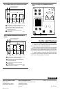
Fig. 2—Internal schematic and typical hookup
for RA89A.