


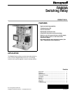

RA889A SWITCHING RELAY
68-0216—24
WIRING
WARNING
Electrical Shock Hazard.
Can cause serious personal injury or death.
Use only NEC Class 1 wire for all line voltage wiring
connections. Class 1 wires must be rated for at least
167°F (75°C).
All wiring must comply with all applicable electrical codes,
ordinances, and regulations. Follow all instructions furnished
with the controlled equipment.
IMPORTANT
The switching relay terminals are approved only for
use with copper wires.
When two or more line-voltage load devices are to be
controlled in parallel, the total current must not exceed the
rating for the relay load. Never connect load terminals to a
load that uses more current than the amount listed in the
electrical ratings on the relay. See Table 3 for wiring length
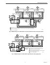
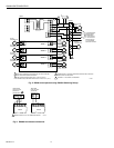
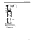
specifications. See the schematic and typical hookups in Fig.
2 through 7.
Table 2. Wire Lengths.
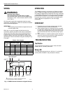
Fig. 2. RA889A internal schematic and typical hookup.
OPERATION
The RA889A consists of a transformer, an Spdt line-voltage
relay, an Spst low-voltage relay and wiring terminals. When
line-voltage is applied to the transformer, the relay is powered
on thermostat contact closure. The relay may also be used to
provide electrical isolation in low-voltage circuits, if powered
from a 24 Vac or 24 Vdc external source connected to W(T)
and C. Fiber barriers separate line- and low-voltage
connections.
CHECKOUT
1.
Keep the cover on the relay during normal operation
and remove only for service and checkout.
2.
Relay contacts require no cleaning; they are arranged
to close with a wiping action and are self-cleaning. The
contacts may turn black after being in service for some
time; this discoloration does not prevent proper opera-
tion.
3.
After installation is complete, operate system through at
least one cycle from the controller to make certain the
relay controls the equipment as intended.
.TROUBLESHOOTING
Test Button
This connection is the same as a call for heat connection
between the R(T) and W(T) terminals.
Relay LED
This LED lights whenever there is 120 Vac (L1) on the N.O.
terminal (when COM/N.O. relay contacts are closed).
Wire Size
(AWG)
Total Wire Length
Wire Length of Run to
Thermostat
Feet Meters Feet Meters
22 120 38.0 60 18.0
20 200 61.0 100 30.5
18 300 91.5 150 45.5
16 500 152.5 250 76.0
14 800 244.0 400 122.0
L1
HOTL2
R(T) W(T)
C
L2 L1
1
1
LOW VOLTAGE (CLASS 2)
2-WIRE THERMOSTAT
POWER SUPPLY. PROVIDE OVERLOAD PROTECTION
AND DISCONNECT MEANS AS REQUIRED.
X2X1
RELAY
LED
LOW-VOLTAGE
POWERPILE®
G
N.O.COM
TO
POWER
N.C.
LOAD 1
TO
POWER
1
M14295
AUTOMOTIVE
FUSE