


Hubbell Industrial Controls, Inc.
A subsidiary of Hubbell Incorporated
4301 Cheyenne Dr., Archdale, NC. 27262
Telephone (336) 434-2800 • FAX (336) 434-2803
http://www.hubbell-icd.com
Sales@hubbell-icd.com
Brass inserts molded into the flyweight
housing retain the 2 shaft bearings.
Speed Adjustment - Speed points at which
contacts operate are easily adjustable in the
field within the standard operating ranges.
Switches are factory-set at minimum as-
cending speeds as listed in the Price List
2210. Other contact settings may be speci-
fied as an option. EACH SET OF SNAP-
ACTION INDEPENDANTLY ADJUSTABLE
FROM THE REAR WHILE THE SWITCH IS
ROTATING. Also the speed setting of both
sets of contacts can be changed at the same
time by varying the tension on the adjustment
spring with the adjustment nut. Turning the
spring adjustment nut or the contact adjust-
ment screws in a clockwise direction will
cause the contacts to operate at a higher
speed, but making these adjustments in a
counter-clockwise direction will cause the
contacts to operate at a lower speed.
Contact - The contact compartment provides
several basic contact-making means as re-
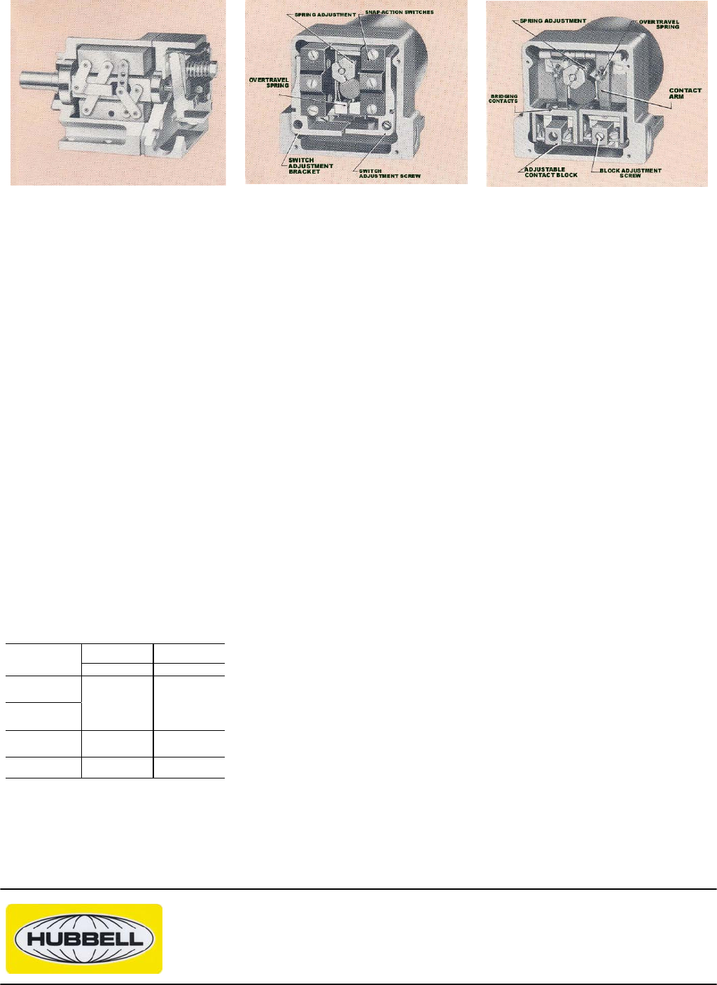
quired for various applications. Slow-action
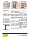
butt-type bridging contacts for rapid speed-
change conditions or snap-action contacts for
slow speed changes can be supplied.
One set or two sets of normally open and/or
normally closed single-throw contacts …
each set independently adjustable … are
available in the slow-action type. One set or
two sets of normally open and normally
closed single-pole, double-throw, snap-action
switches are also available with each set
independently adjustable.
These two separate sets of contacts can be
adjusted for operation at different speeds so
that two separate operations can be con-
trolled from one speed sensitive switch.
Therefore, it is possible to perform two differ-
ent functions at two different speeds.
A directional sensing form of the switch em-
ploys slow-action butt-type bridging contacts
in normally open position only.
Type C Centrifugal Switches are available for
operating in various speed ranges of adjust-
ment between 10 and 4700 RPM on in-
creasing speed. The specific range of ad-
justment that is selected determines the fly-
weight assembly and the adjustment spring
that is used.
The contact adjustment ranges of centrifugal
switches with 2 contacts (shown in the table
of the price list) are for both contacts operat-
ing simultaneously. The 2 contacts can be
adjusted independently, however, that opera-
tion changes the adjustment range from that
shown.
The ranges of adjustment listed are for
switches mounted horizontally. Vertically
mounted switches with the shaft extension
down have different ranges of adjustment. A
special wide range adjustment can be sup-
plied on special order.
The recommended maximum running speed
of a switch with heavy flyweights is 1800
RPM, with medium flyweights is 4000 RPM
and with light flyweights is 5000 RPM.
OPTIONAL FEATURES
Manual Reset - When specified, EUCLID
Type C Centrifugal Switches can be fur-
nished with one or two manual reset buttons
(one for each set of A-C precision contacts).
A metal guard prevents accidental damage to
the buttons by impact. The Code Letter "M"
designates one set of manually reset A-C
snap-action contacts.
Flexible Couplings - A Flexible Coupling
should be used to connect the Centrifugal
Switch shaft to customer's shaft in order to
compensate for minor misalignment of the
shafts. Couplings can be supplied with a
1/2", 5/8" or 3/4" bore for customer's shaft
and a 5/8" bore for our shaft. Standard key-
ways can be furnished. Specify by catalog
number on Price List 2210.
Magnetic Vibration Dampeners - counter-
acts destructive action of the "dither". Spec-
ify by catalog number on Price List 2210.
Air Valve Actuating - Type AV, air valve
instead of electrical contacts for pneumatic
systems. Refer to factory with application
data.
Speed Increaser - 3 to 1 ratio can be
mounted at the factory which permits the
input shaft speed of the speed increaser to
be 1/3 the normal input shaft speed. Specify
by suffix number "S" for Single Speed In-
creaser and "SS" for Double Speed In-
creaser. Refer to Price List 2210.
AMPERES
MAXIMUM CONTACT INTERRUPTING RATINGS
AC 35% PF
DC
INDUCTIVE
TYPE OF
CONTACT
120v 240v 480V 125v 250v
*SLOW ACTION
Non Directional
(Butt-Type)
*SLOW ACTION
Directional
(Butt-Type)
3 15 .75 .75 .35
*SNAP ACTION
AC Type
3 1.5 .75 .25 .12
*SNAP ACTION
DC Type
……… .60 .25
* Rating based on a min. of 1/32" contact gap.
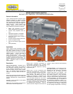
CUT
-
AWAY VIEW
SNAP
-
ACTION CONTACTS
SLOW
-
ACTION CONTACTS