


Features
Microcomputer
Hubbell’s system uses a
single board micro com-
puter which converts the
biphase data from the ra-
dio receiver, decodes and
verifies the message by
checking for errors. The
computer generates the
control outputs to the l/O
interface boards. The ad-
dress and message time
interval is user program-
mable. A hardware
watchdog timer monitors
the program operation
and resets the processor if
the program fails to exe-
cute properly.
On-Board Diagnostics
The computer board em-
ploys continuous diagnos-
tics. System status is dis-
played on a two digit al-
pha numeric display.
Upon power-up, the initial-
ization test checks the I/O
boards, internal random
access memory (RAM), the
motion controlling solid
state relays, and the pneu-
matic system.
When a fault is detected,
the computer will stop the
locomotive and the error
will be displayed. The
fault must be corrected
before operation can
continue.
After initialization, the
watchdog circuit, the solid
state relays and the pneu-
matic functions are contin-
uously monitored. Any op-
erational, communications
or run mode faults will
shutdown the locomotive,
apply the brakes, and dis-
play a fault code.
Input/Output Board
The l/O board accepts
the control outputs from the
microcomputer and con-
verts them into driving out-
puts for the solid state re-
lays. The l/O board also
accepts input from the sol-
id state relays feedback
circuits and provides this
information to the controller
for diagnostic purposes.
Emergency Stop Board
The Emergency Stop
board monitors the Emer-
gency Stop pushbuttons
mounted in the locomo-
tive, the main air reservoir
pressure, oil pressure, and
coolant water tempera-
ture. If any of these func-
tions are abnormal, a sig-
nal is given to the micro to
shut down the locomotive
and apply the brakes.
DC Solid State Output
Each solid state relay
board has eight circuits to
drive the 24VDC interfac-
ing relays and solenoid
valves to control the loco-
motive functions.
Electro-Mechanical
Relays
Electro-Mechanical Relays
are used to control loco-
motive direction, throttle,
head lamps, and Lintern
lights. The Lintern lights
provide operations status
information for the remote
operator.
Sensing Boards
Each sensing board moni-
tors up to eight solid state
relay outputs and/or pres-
sure switches. This pro-
vides complete feedback
to the micro on relay and
pressure switch status.
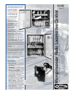
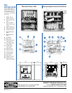
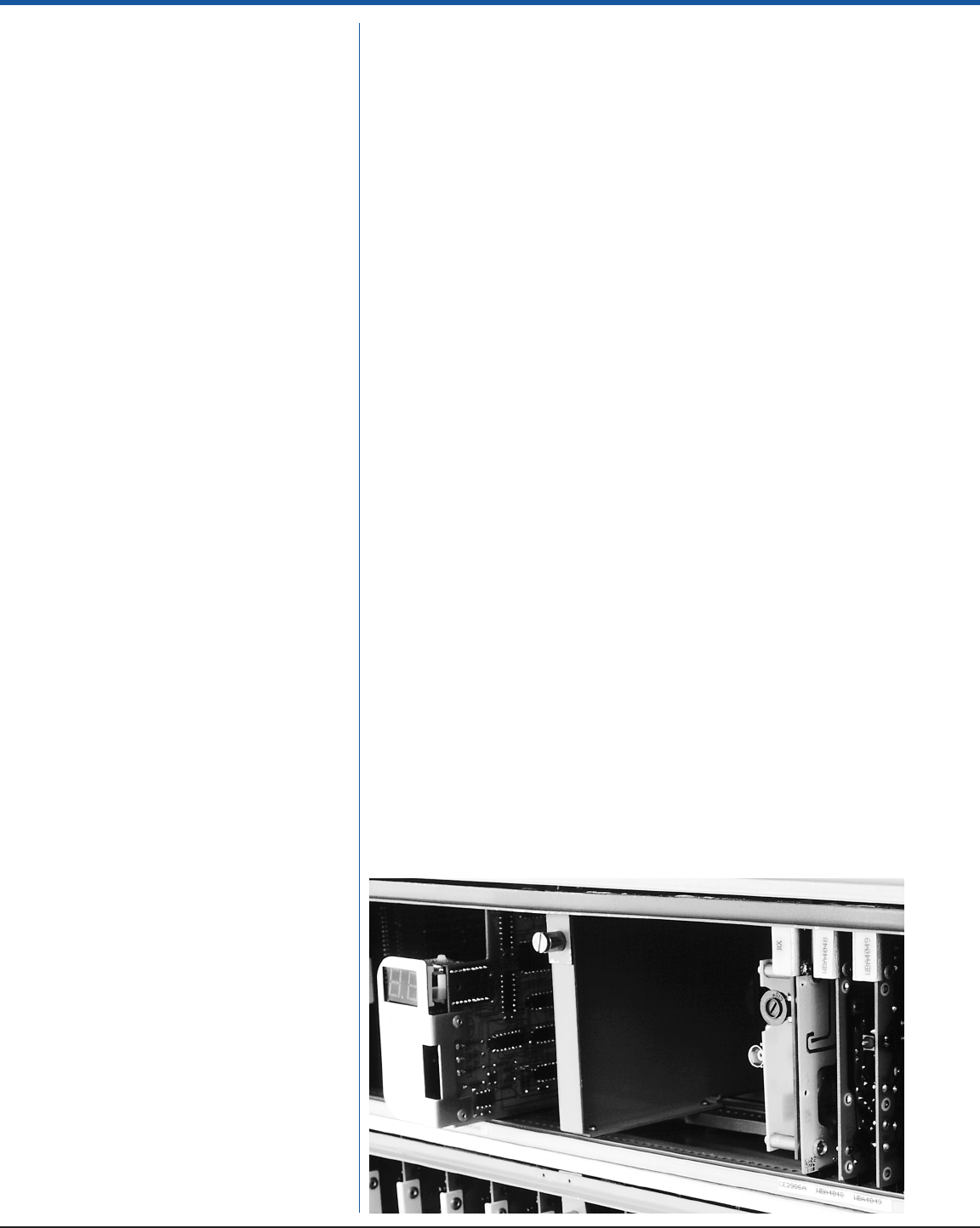
Receiver Cabinet
The electronics cabinet is
of NEMA 12 construction
and houses the power
supply, the radio receiver,
digital decoding logic
cards, solid state drivers
and the output relays.
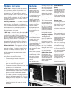
The receiver, digital logic
decoding circuits and the
solid state drivers plug
into common card cag-
es. Edgemounted LED’s
on the circuit boards sim-
plify system troubleshoot-
ing and maintenance
tasks. All modules are re-
movable from the front
and the card cage is
hinged to provide access
to backplane wiring.
Solid state drivers or out-
put relays operate the lo-
System Features
Secure Control — Hubbell’s biphase data transmis-
sion scheme and Cyclic Redundency Check code
(CRC) prevent false motions and provides for con-
trolled shutdowns. Digital messages are checked for
address, format, and content before any motion or
function is activated. While in motion, check circuits
continuously monitor the received message and the
quality of the RF carrier signal. Any error or loss of sig-
nal integrity will de-energize all controlled functions
and apply the brakes.
Frequency Conservation — It is possible to have sev-
eral transmitters operating in the same area, on the
same frequency, with practically no interference be-
cause of different transmission rates for each transmit-
ter. The unique address code of each transmitter and
receiver assures that only the matching receiver re-
sponds to the radio commands. All other signals on
the same frequency are ignored.
“QSR” Design — Hubbell’s Quality, Serviceable, Reli-
able product design philosophy is evident with the Lo-
comotive Control System. Protective circuits are em-
ployed to prevent transients or extreme voltage fluctua-
tions from damaging components. The modular, solid
state design, housed in NEMA 12 enclosures, pro-
vides reliable operation and long service life under
the most rugged and extreme conditions. Spares re-
quirements are significantly reduced by virtue of the
shared frequency capability and modular design.
Efficient and Flexible — The high speed data trans-
mission technique provides faster and thereby more
responsive operation. A lightweight, durable plastic
transmitter is comfortable and easy to operate. A
manual/remote transfer switch can be provided for
isolation between the manual and remote control
components.
Security of the received signal and any resulting con-
trol actions are safeguarded as follows:
• The received signal must be of the proper
frequency.
• The received message must have the proper ad-
dress and must be in the correct format.
• The receiver calculated CRC code must be identi-
cal to the CRC code calculated by the transmitter
and sent as part of each message.
• The preceding items must be met and all transmitter
lever switches must be centered before the locomo-
tive can be activated and the brakes released.
• To continue or change an energized function, re-
quires the receipt of a “valid message” prior to
time-out of the message timer (2 sec). If no valid
message is received, the system turns all outputs
off and applies the brakes.
• Two separate “watchdog timers” assure that all
outputs are switched off in case of a receiver
malfunction.