


Euclid Lifting Magnet Controllers: Automatic Discharge Specifications 4291
period, controlled by the Potentiometer (P1)
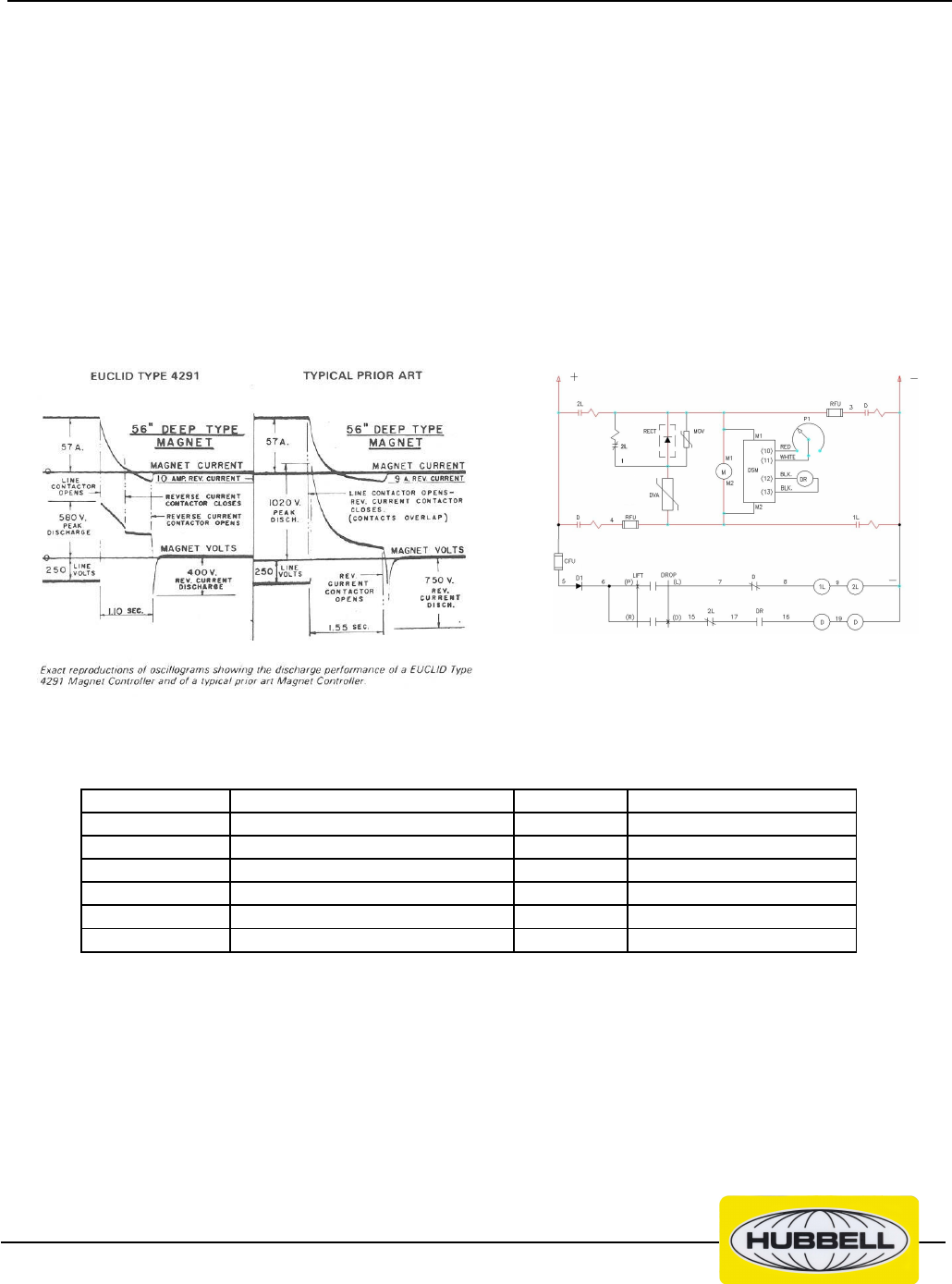
assembly, the DSM de-energizes the Drop
Relay. This causes the Drop contactor to
open and end the reverse current cycle.
The remaining reverse magnet current flows
through a secondary discharge path from the
magnet through the normally closed "power
auxiliary" interlock of 2L, the DVA and back
to the magnet.
The Euclid magnet controller can be operated
by a small notched position master switch or
a maintained contact-type pushbutton station.
The arrangement of the circuit components
allows an operator to drop portions of a load
with ease. This is a feature most operators
will appreciate. A portion of the load can be
dropped by merely moving the master switch
only the distance necessary to momentarily
de-energize the "Lift" contactor. This feature
is possible because of the permanently con-
nected discharge path and the elimination of
having to close the "Drop" contactor before
opening the "Lift" contactor.
FANNING PACKAGE includes Fanning Con-
tactor and Fanning Resistor for separate
mounting suitably enclosed for NEMA 2 or
NEMA 3R service.
Fanning is the insertion of a resistor dis-
charge path in parallel with the DVA to give
extended magnet discharge time that is acti-
vated by a separate fanning pushbutton. The
operator is allowed to control the rate of mag-
net discharge, dropping all or part of the load,
by activating the fanning control. Releasing
the fanning pushbutton deactivates the fan-
ning control and returns the magnet controller
to the lift mode to retain the remaining mag-
net load.
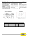
Comparison ChartSchematic Diagram Schematic Diagram
Symbol Function Symbol Function
DR DROP RELAY MOV SURGE SUPPRESSOR
PI POTENTIOMETER ASSEMBLY DVA DISCHARGE VARISTOR
CFU CONTROL FUSE DSM DISCHARGE SENSOR MODULE
RFU DROP FUSE D DROP CONTACTOR
DI DIODE 2L LIFT CONTACTOR
RECT RECTIFIER, MAGNET DISCHARGE PATH 1L LIFT CONTACTOR
Page 2 of 4