


HUBBELL
Troubleshooting 24
Silicon Controlled Rectifiers – SCRs
Troubleshooting
Inverse parallel SCR
bridges control AC
power by providing a
method of adjusting ap-
plied voltage as in the
case of Primary Motor
Control. The AC Power is
handled on a half cycle
basis by one of two
SCR’s. Refer to the Pri-
mary SCR Bridge figure
provided. SCR1 can con-
duct power on the first
half of the cycle and
SCR2 can conduct during
the remaining half of the
cycle thereby providing
balanced currents. Am-
meter readings of motor
primary currents at low
motor speeds should pro-
duce balanced readings.
If one of the SCR’s fails to
conduct, the controlled
power becomes unbal-
anced with a DC compo-
nent which can saturate
common motor loads and
lead to higher than nor-
mal operating currents. If
one of the SCR’s be-
comes shorted, the SCR
Bridge supplies full con-
duction for that phase re-
sulting in unbalanced
phase voltages and cur-
rents in Primary Control.
The operating condition
of an inverse parallel SCR
Bridge can be deter-
mined easily with a digi-
tal DVM. A simple conti-
nuity test can be
performed with the power
removed from the motor
circuit. In most Primary
Control systems, when the
power is removed and
the directional or main
contactor is open, the
SCR Bridge is isolated
and continuity measure-
ments can be made di-
rectly at the bridge. A
shorted SCR will result in
a very low or “Zero”
ohmmeter reading. A
good SCR Bridge will re-
sult in a ohmmeter read-
ing of 200K to 300K
ohms.
An open or nonconduct-
ing SCR as well as a
shorted SCR can also be
located by taking a set of
AC and DC readings
across each SCR Bridge
and comparing the val-
ues. Again, normal read-
ings will be balanced
from phase to phase with
the “odd” reading indi-
cating a problem. By
looking at the SCR Bridge
waveforms on the figures
supplied, normal opera-
tion is indicated by equal
periods of positive and
negative voltage. With
the motor operating at
minimum speed, approxi-
mately 50% voltage will
be supported across
each SCR Bridge, and an
AC measurement across
each bridge should yield
balanced voltages. A
“Zero” or very low AC
voltage reading indicates
a shorted SCR. With the
DVM set to read DC, volt-
age measurements across
each bridge should yield
a low DC value indicat-
ing equal periods of posi-
tive and negative volt-
age. A typical DC
voltage encountered in
this measurement will be
less than 10 volts. A
reading substantially
higher than 10 volts indi-
cates unbalanced firing.
The unbalanced condi-
tion will affect the read-
ings on the remaining two
phases, therefore, the
highest unbalanced volt-
age when compared to
the remaining readings,
indicates the problem
phase.
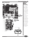
AC Power
SCR Bridge
AC Load
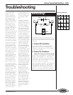
SCR Firing Cycle Waveforms
Minimum
Firing
Medium
Firing
Maximum
Firing
Lockout
No Firing
Minimum
Voltage
Half
Voltage
Maximum
Voltage
Zero
Voltage
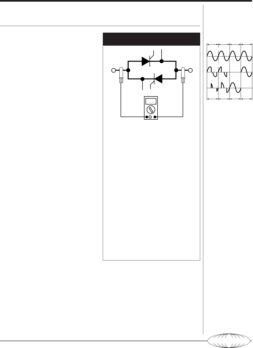
SCR Readings
SCR1
Line Load
SCR2
DVM
Connecting a DVM as shown above, test an
SCR for the two conditions listed below. If either
of the test conditions fail the SCR will need to be
replaced.
1. Power Off Condition
Set the DVM to Ohms and measure the resis-
tance across the SCR. It should read 200k–
300kΩ. If it reads 0Ω, then the SCR is shorted.
It needs to be replaced.
2. Power On Condition
(Motor Running at minimum speed)
Set the DVM to read 600VAC. If the DVM reads
between ≈200–300VAC for a 460V system
configuration, the SCR is acting normal with all
phases balanced. If the DVM reads 0V, the SCR
is shorted. It needs to be replaced.
Now set the DVM to 600VDC. If the DVM read
±5 to ±10VDC, the SCR is running normally
with all phases balanced. If the DVM reads
>±20VDC, the SCR is conducting current as a
diode or is not firing. It needs to be replaced.