


Part No. P807-0198
Rev. B 6/96
INSTALLATION
2
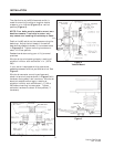
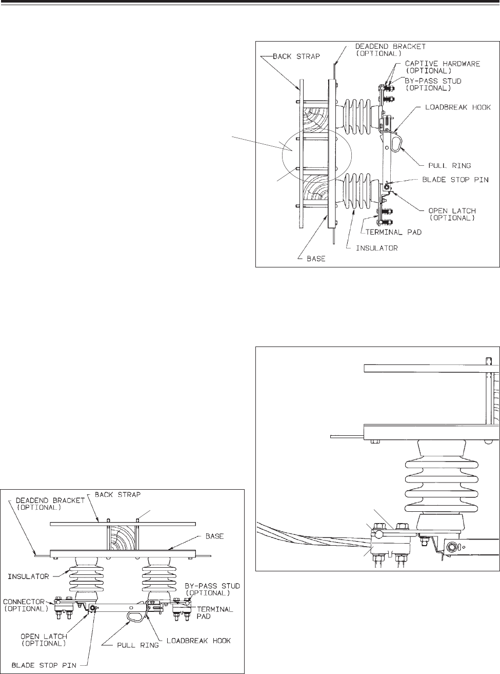
Figure 4
Vertical Mount
(STANDARD)
The distribution style M3 disconnect switch is
made for mounting to either a single or double
crossarm in an inverted (Figure 3) or vertical
position (Figure 4).
NOTE: Four bolts must be used to mount on a
double crossarm. Two bolts in center only
may cause over bending of backstrap or base.
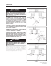
Figure 5
BY PASS
STUD
TERMINAL PAD
TERMINAL
Figure 3 Inverted-Underhung
(STANDARD)
Position the M3 switch on the crossarms using the
backstrap. Adjust the bolt heads in the switch
base slots as needed to closely fit the crossarms as
in Figures 3-4. Tighten mounting hardware to
about 12-15 foot-pounds.
Deadend conductors using your utility’s normal
practices.
Wire brush terminal pads and apply a coating of
oxidation inhibitor such as Chance z.l.n. (100 or
200).
If your switch is equipped with by-pass studs,
assemble between terminal pad and terminal. See
Figure 5.
Wire brush connector mounting surfaces and
attach to terminal pads as shown in Figure 5 with
hardware facing away from insulators. Wire brush
electrical conductors and apply a coating of
oxidation inhibitor such as Chance z.l.n. (100 or
200) before inserting into connector. Tighten
connector hardware to about 30 foot-pounds (
1
/2"
hardware).
NUTS &
WASHERS
THIS SIDE
ONLY
NUTS & WASHERS
THIS SIDE ONLY