


4 3004090-0001 Revision A
Step D. Mounting the pole base bracket
You may install the fixed mount on any structurally sound surface; either on a horizontal, or vertical, or a
sloped surface, such as a roof or wall.
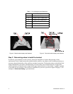
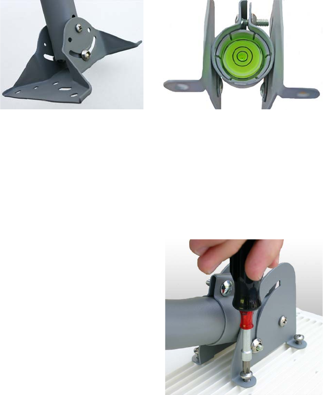
The pole is shipped attached to the base bracket (Figure 5). Mount the base bracket of this assembly to the
structure with the appropriate hardware (not included). Once the base bracket is mounted, perform the
following steps:
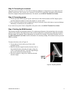
1. Insert the bubble level
(Figure 6) into the end of
the pole (pipe) opposite the
base bracket. The bubble
level fits into a shoulder
inside the pole.
2. Loosen the pole
attachment fasteners at the
base bracket so the pole
can swivel (Figure 5).
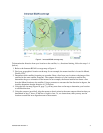
3. Swivel the pole until the
end of the pole where the BGAN terminal will be installed is vertical (as shown in Figure 1). Adjust
the pipe position until the bubble is centered inside the circles on the top surface of the bubble level as
shown in Figure 6.
4. Tighten the pole attachment fasteners on the base bracket (Figure 5).
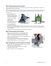
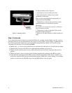
Step E. Mounting the terminal bracket
1. The terminal can be mounted so its light-emitting diodes
(LEDs) and control buttons face up—toward the sky, or
down— toward the ground. Orient the terminal bracket
(Figure 7) so the LEDs will face up or down, depending on how
they can be most easily read.
2. Secure the terminal bracket to the terminal with the four
provided tamper proof ¼ - 20 x 1/2 in. (12.5-mm) bolts. A
special tool with a driver bit is provided (Figure 7).
Step F. Mounting the terminal bracket onto the pole
1. Slide the pole collar of the terminal bracket over the end of the
pole. This collar is shown in Figure 7.
2. Leave the pole collar bolts loose to allow for azimuth
adjustment during pointing.
3. Check to make sure you can read the LEDs.
Figure 5 - Base bracket Figure 6 - Bubble level
Figure 7 - Terminal bracket