


SCSI-ENET Controller
- The SCSI-ENET controller is the interface between the system bus and the SCSI
and Ethernet I/O devices. It contains four differential SCSI interface ports (used for interfacing with mass
storage devices such as the D700 disk/tape subsystem and T204/T403 tape drives) and one Ethernet port. Each
pair of SCSI-ENET controllers can support up to 48 physical disk drives.
IO Processor
- The IO processor manages IO operations, primarily to IOA communications adapters and
certain peripheral devices. It interfaces the system bus to two 8-bit IO busses. Each pair of IO processors can
support two IOA chassis.
K470 PMC I/O Controller
- High-speed I/O subsystem based on the Peripheral Component Interconnect
(PCI) bus. It provides interconnect to the system backplane for up to three PCI I/O adapters in PMC (PCI
Mezzanine Card) form factor.
CPU-Memory boards reside in four dedicated slots in the backplane. The remaining slots are configured with
SCSI-ENET controllers or IO processors. Recommended slot assignments for various models are shown later in this
document.
The CEC cabinet in an AC system contains an AC/DC power system that provides 3600 watts of N+1 DC power.
The AC/DC power system residing in each expansion cabinet (except the AC peripheral cabinet, which has no power)
provides 2400 watts of N + 1 DC power.
Continuum systems are also designed to be fully Central Office (CO) installable utilizing -48 V DC input power. Each
CEC cabinet and DC expansion cabinet in a CO system contains two DC power controllers.
There is no physical control panel on Continuum 600/1200 Series systems. Operating commands are entered at the
system console which is connected to the system via the Console Controller card in the CEC cabinet.
2. Operating System Requirements
FTX VOS System
Minimum release 3.0 Minimum release 13.0 AC systems
Minimum release 3.0 Minimum release 14.0.1 DC systems
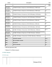
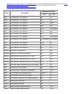
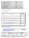
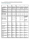
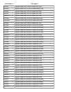
3. Hardware Components
NOTE:
The hardware components shown in the following tables are at the base minimum revisions
approved for operation at the time of publication. For current revision requirements and complete revision
history, refer to the HQ Service Support Rev Dir.
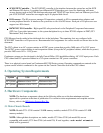
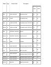
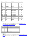
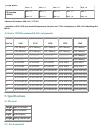
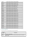
3.1 Main Chassis Boards
NOTE:
Models G731-G748 contain 128-MB memory modules; models G751-G758 contain 512-MB
memory modules.
NOTE:
Although their descriptions are similar, models G731 thru G748 (sub model 00) are not
compatible with models G731 thru G748 (sub model 20). If used together, a sub model mismatch
failure will be generated.