


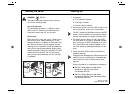

Installing the Switch
DANGER: 55H7211.
The User’s Guide also contains further informa-
tion on the following steps.
Into a 19-inch rack
Fit the brackets as shown in 1 (below) to each
side of the unit. Following the manufacturer’s
instructions, secure the unit into the rack.
On the wall
Place the unit the right way up on a hard flat sur-
face with the front facing towards you. Fit the
brackets as shown in 2 (below) to each side of the
unit. Place the base of the unit against the wall,
ensuring that the ventilation holes face sidewards
and the front panel faces upwards. Secure using
suitable screws and fixings (not supplied). The wall
surface should be smooth, flat, dry and sturdy.
Use a plywood sheet between the unit and wall
if necessary.
Powering Up
1
As required:
a
Fit a Transceiver Module
b
Fit a Plug-in Module
c
Connect network cabling
2
Connect the power cord to the IEC socket on the
rear of the Switch, and to your mains socket.
The 8271 Model 612/624 Switch has no ON/OFF
switch, the only method of connecting or discon-
necting mains power is through the power cord.
3
The Switch enters a Power On Self Test (POST).
The time taken for the test to complete is depen-
dent on the type of POST configured for the unit.
For a new Switch that is being installed for the
first time, power-up takes approximately 13 sec-
onds.
4
Check the status LEDs to ensure the Switch is
operating correctly.
Intelligent Flow Management (IFM) should be dis-
abled if the port is connected to a repeated seg-
ment where the traffic is mainly local to that
segment.
Further information on these steps is available in:
IBM 8271 Nways Ethernet LAN Switch
Models 612 and 624 User’s Guide,
Part Number 55H7211
IBM 8271 Nways Ethernet LAN Switch
Models 612 and 624 Quick Reference Guide,
Part Number 55H7212
Part No. 02L1348
Published October 1997