


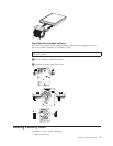
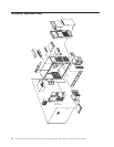
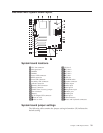

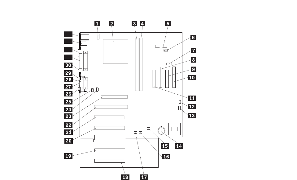
A40/A40P/A40i system board layout
32
31
33
34
System board locations
1CPU fan connector 18PCI slot 5
2Microprocessor 19 PCI slot 4
3DIMM 0 20 PCI slot 3
4DIMM 1 21 PCI slot 2
5Power LED connector 22 PCI slot 1
6RFID connector 23 AGP slot
7Front USB connector 24 CD-ROM audio
8Secondary IDE connector 25 Speaker connector
9Diskette connector 26 Audio output
10Primary IDE connector 27 Audio input
11Power connector 28 Serial port 2
12CMOS clear/recovery jumper 29 Microphone input
13Fan connector 30 Monitor port
14Battery 31 Parallel port
15SCSI adapter LED connector 32 Serial port 1
16 Alert on LAN 33 USB connectors
17 Wake on LAN 34 Mouse and keyboard connectors
System board jumper settings
The following table contains the jumper setting information. (D) indicates the
default setting.
Chapter 5. FRU Replacements 29