USER RESPONSIBLE FOR VERIFYING VERSION AND COMPLETENESS
OEM FUNCTIONAL SPECIFICATION ULTRASTAR XP (DFHC) SSA MODELS 1.12/2.25 GB - 1.0" HIGH
4.2 Carrier Models (CxB)
The carrier model assemblies include the disk drive, drawer mounting hardware (rails, latching mechanism,
and connector), and DC/DC power converter.
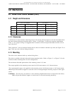
4.2.1 Weight and Dimensions
C1B & C2B Models C4B Models
U.S. S.I. Metric U.S. S.I. Metric
Weight 2.00 pounds 0.92 kilograms 2.80 pounds 1.288 kilograms
Height 1.75 inches 44.5 millimeters 1.75 inches 44.5 millimeters
Width 4.26 inches 108.3 millimeters 4.26 inches 108.3 millimeters
Depth 10.72 inches 272.3 millimeters 10.72 inches 272.3 millimeters
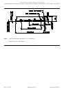
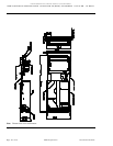
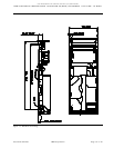
Refer to Figure 15 on page 58 for detailed dimensions.
4.2.2 Clearances
For proper cooling, a clearance of 6 millimeters should be provided above and below the carrier surfaces.
Adequate airflow is needed in order to meet the operating specifications. Maximum temperatures are speci-
fied for critical drive components in Table 15 on page 78.
4.2.3 Mounting
The drive can be mounted with any surface facing down.
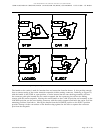
The carrier is designed to be plugged into an auto-docking assembly. The auto-docking assembly contains
an electrical receptacle that provides connections for DC power, SSA interface signals, and fault sensing and
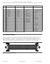
reporting signals (see 5.2, “Carrier Connector” on page 64). The carrier design allows for positive retention
of the carrier in all axes when plugged into the auto-docking assembly. In addition, the carrier retention
provides a force to bottom out the carrier auto-docking connector into the auto-docking assembly and main-
tain a force of 5 pounds minimum, 40 pounds maximum.
The mating connector should contain two guide pins to align the carrier receptacle during seating. These
guide pins are BERG part number 77693-014 (IBM part number 72G0343) or AMP equivalent part number
1-532808-1 (IBM part number 19G6789). The guide pin length should be 26.04 millimeters while the thread
depth depends upon the thickness of the circuit board the connector is mounted to. The guide pins should
be tied to the docking assembly frame ground.
Note: The connector pins must be lubricated to insure seating of the carrier into the auto-docking assembly.
The type of lubricant recommended is Stauffer CL-920 or equivalent.
WARNING: The drive may be sensitive to user mounting implementation due to frame distortion effects.
IBM will provide technical support to assist users to overcome mounting sensitivity.
Source filename=MECHANIC IBM Corporation Page 57 of 87


