


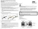
Host-side fibre channel cabling
Attention:
Install the DS4400 Storage Server and all storage expansion enclosures in the rack
cabinet before cabling the configuration.
1. Connect a host adapter to the Host 1 (top) port on host-side mini hub 1. For redundancy,
connect a second host adapter to the Host 1 (top) port on the host-side mini hub 2.
Note:
To connect devices to each other, follow the procedure on the other side of this
document for installing SFP modules and fibre channel cables.
2. For a second redundant host, connect two host adapters to the Host 2 (bottom) ports on host-
side mini hubs 1 and 2.
3. For a third redundant host, connect two host adapters to the Host 3 (bottom) ports on host-
side mini hubs 3 and 4.
4. For a fourth redundant host, connect two host adapters to the Host 4 (top) ports on host-side
mini hubs 3 and 4.
Storage expansion enclosure support
The DS4400 Storage Server enables you to mix certain storage expansion enclosure models in
the same storage server configuration. In some cases, to intermix storage expansion enclosure
models you must meet additional requirements such as firmware updates or grouping restrictions.
To intermix fibre channel and SATA drives, you must purchase the FC/SATA Enclosure Intermix
premium feature. The DS4400 supports up a maximum of 224 drives in two redundant drive loop
pairs.
Refer to the
IBM TotalStorage DS4000 Hard Drive and Storage Expansion Enclosure Installation
and Migration Guide
for complete information on storage expansion enclosure support and
intermixing requirements for the DS4400 Storage Server.
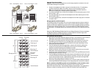
Drive-side fibre channel cabling
1. Start with the first storage expansion enclosure of Group 1 and connect the In port on the left
ESM board to the Out port on the left ESM board of the second (next) enclosure.
2. Start with the first storage expansion enclosure of Group 1 and connect the In port on the
right ESM board to the Out port on the right ESM board of the second (next) enclosure.
3. If you are cabling more storage expansion enclosures to this group, repeat steps 1 and 2,
starting with the second enclosure.
4. If you are cabling a second group, repeat step 1 to step 3 and reverse the cabling order;
connect from the Out ports on the ESM boards to the In ports on successive storage
expansion enclosures according to the illustration on the left.
5. Connect the Out port of drive-side mini hub 4 (left-most drive side) to the In port on the left
ESM board of the last storage expansion enclosure in Group 1.
6. Connect the In port of drive-side mini hub 3 to the Out port on the right ESM board of the first
storage expansion enclosure in Group 1.
7. If you are cabling a second group, connect the Out port of drive-side mini hub 2 to the In port
on the left ESM board of the first storage expansion enclosure in Group 2; then, connect the
In port of the drive-side mini hub 1 (right-most drive side) to the Out port on the right ESM
board of the last storage expansion enclosure in Group 2.
8. Ensure that each storage expansion enclosure has a unique ID (switch setting) and that the
left and right ESM board switch settings on each storage expansion enclosure are identical.
IBM is a trademark of the IBM Corporation in the United States or other countries or both.
© Copyright International Business Machines Corporation 2005. All rights reserved.
Note to U.S. Government Users - Documentation related to restricted rights - Use, duplication or
disclosure is subject to restrictions set forth in GSA ASP Schedule Contract with IBM Corp.
OUT
IN
!
2 Gb/s1 Gb/s
OUT
IN
!
2 Gb/s1 Gb/s
OUT
IN
!
2 Gb/s1 Gb/s
OUT
IN
!
2 Gb/s1 Gb/s
OUT
IN
!
2 Gb/s1 Gb/s
OUT
IN
!
2 Gb/s1 Gb/s
OUT
IN
!
2 Gb/s1 Gb/s
OUT
IN
!
2 Gb/s1 Gb/s
Host 1, Host Adapter 1 and 2 Host 4, Host Adapter 1 and 2
Host 2, Host Adapter 1 and 2 Host 3, Host Adapter 1 and 2
Host 1 Host 4
Host 2
Host 3
In ports Out ports
Drive loop A
Drive loop B
Drive loop C
Out ports
In ports
Drive loop D
Storage server
Group 1
Group 2
Last enclosure
First enclosure
First enclosure
Last enclosure