


2
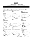
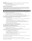
Step 4
Rotate and attach the display bezel.
Step 5
Attach the top panels and mounting stabiliz-
ers.
Step 6
Rotate the unit to tower posi-
tion.
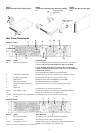
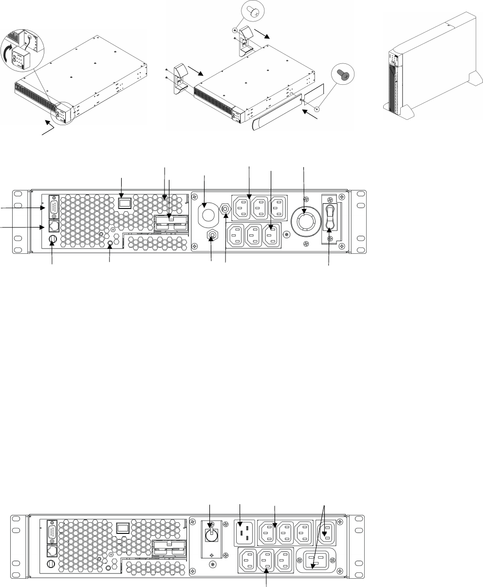
Rear Panel Components
3000XLV Model
INDEX ITEM DESCRIPTION
1 & 2 Serial Port & USB Port
Power management software and interface kits can be used with the
UPS. Use only interface kits supplied or approved by IBM.
Use the supplied serial cable to connect to the serial port. DO
NOT use a standard serial interface cable since it is incompatible
with the UPS connector.
Serial and USB ports cannot be used simultaneously.
3 Voltage Selection Switch See UPS Operation & Setup Guide/Setting the Nominal Voltage.
4 Site Wiring Fault LED See UPS Operation & Setup Guide/Troubleshooting.
5 Network Port Manage the UPS via the Embedded Network Module.
6 Network Reset Button Reset the Embedded Network Module.
7 Extend Run Battery Pack Con-
nector
See Extend Run Battery Pack Operation and Setup Guide.
8 Input Cord
See UPS Operation & Setup Guide/Startup.
9, 10 &
11
Outlet Banks 1, 2 & 3 Separate outlet banks are controlled by the Embedded Network
Module. See Embedded Network Module CD.
12, 13 &
14
Circuit Breakers for Outlet Banks
1, 2 & 3
See UPS Operation & Setup Guide
/Troubleshooting.
3000XHV Model
INDEX* ITEM DESCRIPTION
1 Input Circuit Breaker
See UPS Operation & Setup Guide
/Troubleshooting.
2 Input Connector
See
UPS Operation & Setup Guide/ Startup.
3, 4 & 5 Outlet Banks 1, 2 & 3 Separate outlet banks are controlled by the Embedded Network
Module. See Embedded Network Module CD.
*Exceptions from the 3000XLV are indicated here.
3
(A)
(B)
(A)
(B)
2
3
5
4
12
6
13
8
5
4
2
1
10
11
14
1
Philips Pan Head
8-32 x .375”
x
4
Philips Pan Head
8-32 x .375”
x
1
7
9