PCI-6871 User’s Manual 20
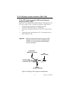
2.16 IR connector (CN9)
This connector supports the optional wireless infrared transmitting and
receiving module. This module mounts on the system case. You must
configure the setting through BIOS setup.
2.17 Audio interfaces (CN10)
The Audio link is a 10 pin connector; the PCI-6871 can support AC97
Audio with the addition of optional PCM-231A-00A1.
2.18 COM port connector (CN19, CN20)
The PCI-6871 provides two serial ports (COM1:RS-232; COM2: RS-
232/422/485) in one COM port connector. The COM port connector is a
40-pin, dual-inline, male header. It provides connections for serial
devices (a mouse, etc.) or a communication network. You can find the pin
assignments for the COM port connector in Appendix C.
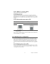
2.18.1 COM2 RS-232/422/485 setting (JP3)
COM2 can be configured to operate in RS-232, RS-422, or RS-485 mode.
This is done via JP3
2.19 VGA/LCD/LVDS interface connections
The PCI-6871’s PCI SVGA interface can drive conventional CRT dis-
plays and is capable of driving a wide range of flat panel displays, includ-
ing passive LCD and active LCD displays. The board has three
connectors to support these displays: one for standard CRT VGA moni-
tors, one for flat panel displays, and one for LVDS type LCD panels.
JP3: COM2 RS-232/422/485 select
PINS RS-232* RS-422 RS-485
1-2 Closed Open Open
3-4 Open Closed Open
5-6 Open Open Closed


