


Chapter 6: Connector Pin Assignments
Input/Output Connections
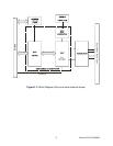
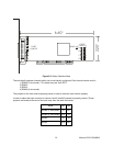
The card’s Serial Communications card uses eight individual 9-pin connectors, provided via a spider
cable from a 68-pin HVDCI D-connector.
To ensure that there is minimum susceptibility to EMI and minimum radiation, it is important that the card
mounting bracket be properly screwed into place and that there be a positive chassis ground. Also,
proper EMI cabling techniques (cable connect to chassis ground at the aperture, shielded twisted-pair
wiring, etc) be used for the input/output wiring.
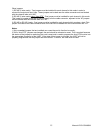
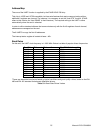
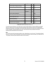
DB-9 Male Pin for each of Ch A-G RS-232 Signals
(Industry Standard)
RS-485 Signals
(2 Wire)
RS-422 Signals
(Also 4wire RS485)
Ch x - 1 DCD RX-/TX-
1
RX-
Ch x - 2 RX TX+/RX+
1
TX+
Ch x - 3 TX TX-/RX-
1
TX-
Ch x - 4 DTR
Ch x - 5 Gnd Gnd Gnd
Ch x - 6 DSR
Ch x - 7 RTS
Ch x - 8 CTS
Ch x - 9 RI RX+/TX+
1
RX+
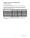
Table 6-1: Connector Pin Assignments
1
RS485 (2 wire) requires the installation of jumpers on the card to properly connect these pins. When
using the spider cable, the appropriate DB 9 connectors will have pin 1 connected to pin 3 and pin 2 is
connected to pin 9.
Manual LPCI-COM-8SM
19