


Appendix A: Application Considerations
Introduction
Working with RS422 and RS485 devices is not much different from working with standard RS232 serial
devices and these two standards overcome deficiencies in the RS232 standard. First, the cable length
between two RS232 devices must be short; less than 50 feet at 9600 baud. Second, many RS232 errors
are the result of noise induced on the cables. The RS422 standard permits cable lengths up to 5000 feet
and, because it operates in the differential mode, it is more immune to induced noise.
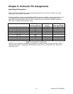
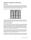
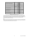
Connections between two RS422 devices (with CTS ignored) should be as follows:
Device #1 Device #2
Signal Pin No. Signal Pin No.
Gnd 5 Gnd 5
TX
+
2 RX
+
9
TX
-
3 RX
-
1
RX
+
9 TX
+
2
RX
-
1 TX
-
3
Table A-1: Connections Between Two RS422 Devices
A third deficiency of RS232 is that more than two devices cannot share the same cable. This is also true
for RS422 but RS485 offers all the benefits of RS422 plus allows up to 32 devices to share the same
twisted pairs. An exception to the foregoing is that multiple RS422 devices can share a single cable if only
one will talk and the others will all receive.
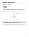
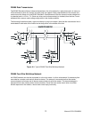
Balanced Differential Signals
The reason that RS422 and RS485 devices can drive longer lines with more noise immunity than RS232
devices is that a balanced differential drive method is used. In a balanced differential system, the voltage
produced by the driver appears across a pair of wires. A balanced line driver will produce a differential
voltage from +2 to +6 volts across its output terminals. A balanced line driver can also have an input
"enable" signal that connects the driver to its output terminals. If the "enable signal is OFF, the driver is
disconnected from the transmission line. This disconnected or disabled condition is usually referred to as
the "tristate" condition and represents a high impedance. RS485 drivers must have this control capability.
RS422 drivers may have this control but it is not always required.
A balanced differential line receiver senses the voltage state of the transmission line across the two signal
input lines. If the differential input voltage is greater than +200 mV, the receiver will provide a specific
logic state on its output. If the differential voltage input is less than -200 mV, the receiver will provide the
opposite logic state on its output. A maximum operating voltage range is from +6V to -6V allows for
voltage attenuation that can occur on long transmission cables.
A maximum common mode voltage rating of +7V provides good noise immunity from voltages induced on
the twisted pair lines. The signal ground line connection is necessary in order to keep the common mode
voltage within that range. The circuit may operate without the ground connection but may not be reliable.
Manual LPCI-COM-8SM
20