


EM78P468N/EM78P468L
8-Bit Microcontroller
12 •
Product Specification (V1.5) 02.15.2007
(This specification is subject to change without further notice)
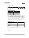
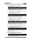
Bit 1 (CNT2EN): Counter 2 enable bit
CNT2EN = “0” : Disable Counter 2. Stop counting operation.
CNT2EN = “1” : Enable Counter 2. Start counting operation.
Bit 0 (CNT1EN): Counter 1 enable bit
CNT1EN = “0” : Disable Counter 1. Stop counting operation.
CNT1EN = “1” : Enable Counter 1. Start counting operation.
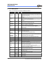
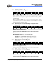
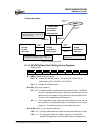
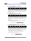
6.1.14 RD/SBPCR (System, Booster and PLL Control Register)
(Address: 0Dh)
Bit 7 Bit 6 Bit 5 Bit 4 Bit 3 Bit 2 Bit 1 Bit 0
− CLK2 CLK1 CLK0 IDLE BF1 BF0 CPUS
Bit 7: Not used
Bits 6 ~ 4 (CLK2 ~ CLK0): main clock selection bits for PLL mode (code option select)
CLK2 CLK1 CLK0 Main clock Example Fs=32.768K
0 0 0 Fs×130 4.26 MHz
0 0 1 Fs×65 2.13 MHz
0 1 0 Fs×65/2 1.065 MHz
0 1 1 Fs×65/4 532 kHz
1 × × Fs×244 8 MHz
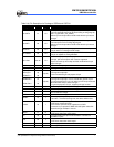
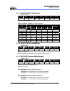
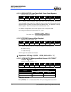
Bit 3 (IDLE): Idle mode enable bit. This bit will determine the intended mode of the
SLEP instruction.
Idle = ”0”+SLEP instruction → Sleep mode
Idle = ”1”+SLEP instruction → Idle mode
* NOP instruction must be added after SLEP instruction.
Example : Idle mode : Idle bit = “1” +SLEP instruction + NOP instruction
Sleep mode : Idle bit = “0” +SLEP instruction + NOP instruction
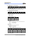
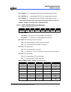
Bits 2, 1 (BF1, 0): LCD booster frequency select bit to adjust VLCD 2, 3 driving.
BF1 BF0 Booster Frequency
0 0 Fs
0 1 Fs/4
1 0 Fs/8
1 1 Fs/16
Bit 0 (CPUS): CPU oscillator source select, When CPUS=0, the CPU oscillator select
sub-oscillator and the main oscillator is stopped.
CPUS = “0”: sub-oscillator (Fs)
CPUS = “1”: main oscillator (Fm)