


Table of Contents
v
Contents
Chapter 1 General Information ........................................1
1.1 Introduction ....................................................................... 2
1.2 Features ............................................................................. 3
1.3 Specifications .................................................................... 3
1.3.1 Standard SBC Functions................................................. 3
1.3.2 VGA/LCD/LVDS Interface............................................ 4
1.3.3LVDS: Supports 2 Channel LVDS interface................4
1.3.4 PCI bus Ethernet interface .............................................. 4
1.3.5 Mechanical and Environmental ...................................... 4
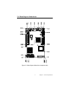
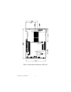
1.4 Board layout: dimensions.................................................. 5
Chapter 2 Installation ........................................................7
2.1 Jumpers.............................................................................. 8
2.2 Connectors......................................................................... 8
2.3 Locating jumpers............................................................. 10
2.4 Locating Connectors ....................................................... 11
2.5 Setting Jumpers ............................................................... 12
2.6 Clear CMOS (JP1) .......................................................... 13
2.7 Installing system memory (SODIMMs).......................... 14
2.7.1 Installing SODIMMs .................................................... 14
2.8 IDE, CDROM hard drive connector (CN1, CN7)........... 15
2.8.1 Connecting the hard drive............................................. 16
2.9 Solid State Disk............................................................... 16
2.9.1 CompactFlash (CN28).................................................. 16
2.10 Floppy drive connector (CN6) ........................................ 16
2.10.1 Connecting the floppy drive .........................................17
2.11 Parallel port connector (CN2) ......................................... 17
2.12 Keyboard and PS/2 mouse connector (CN25) ................ 17
2.13 Power & HDD LED, Reset (CN13, CN8) ...................... 18
2.13.1 Power & HDD LED (CN13) ........................................ 18
2.13.2 Reset switch (CN8).......................................................18
2.14 Power connectors (CN11, FAN1)................................... 18
2.14.1 Main power connector, +5 V, +12 V (CN11).............. 18
2.14.2 CPU Fan power supply connector (FAN1)...................18
2.15 ATX power control connector (CN3, CN5).................... 19
2.15.1 ATX feature (CN3) and soft power switch (CN5) .......19
2.16 IR connector (CN9)......................................................... 20
2.17 Audio interfaces (CN10)................................................. 20
2.18 COM port connector (CN19, CN20)............................... 20
2.18.1 COM2 RS-232/422/485 setting (JP3)........................... 20
2.19 VGA/LCD/LVDS interface connections ........................ 20
2.19.1 CRT display connector (CN12).................................... 21