


179
CHAPTER 12 INTERRUPT FUNCTION
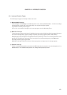
(4) External interrupt mode register (INTM0, INTM1)
These registers set the valid edge for INTP1 to INTP3.
INTM0 and INTM1 are set by 8-bit memory manipulation instructions.
RESET input sets these registers to 00H.
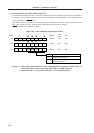
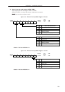
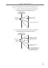
Figure 12-5. External Interrupt Mode Register 0 Format
Caution Set 0 to the bits 0 to 3.
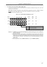
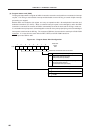
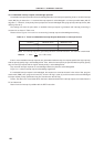
Figure 12-6. External Interrupt Mode Register 1 Format
Address
FFECH 00H
After
Reset
R/W
R/W
7
ES31
Symbol
INTM0
6
ES30
5
ES21
4
ES20
3
0
2
0
1
0
0
0
0
0
1
1
INTP1 Valid Edge Selection
Falling edge
Rising edge
Setting prohibited
Both falling and rising edges
ES21
0
1
0
1
ES20
0
0
1
1
INTP2 Valid Edge Selection
Falling edge
Rising edge
Setting prohibited
Both falling and rising edges
ES31
0
1
0
1
ES30
Caution Set 0 to the bits 2 to 7.
Address
FFEDH 00H
After
Reset
R/W
R/W
0
0
1
1
INTP3 Valid Edge Selection
Falling edge
Rising edge
Setting prohibited
Both falling and rising edges
ES41
7
0
Symbol
INTM1
6
0
5
0
4
0
3
0
2
0
1
ES41
0
ES40
0
1
0
1
ES40