


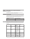

Table 2. Fansink numbers by System Board Assembly and FRU
Numbers (continued).
Machine Type FRU Part Numbers System Board
Assembly Part
Numbers
Fansink Number
7043–150 375MHZ
New Version System
Board
08L8446, 11K0157,
11K0459 41L5177,
41L5912, 41L5518
41L5590
03N2526, 08L1363,
11K0148 11K0464,
41L5172, 41L5517
41L5588, 41L5911
09P1126
7043–150 375MHZ
New Version System
Board
11K0459, 41L5912 11K0017, 11K0650 09P1129
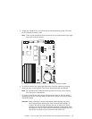
7043–140 and 7043–150 Fansink Removal and Replacement Procedures
This section contains instructions for removing and replacing defective fansinks on both
the 7043–140 and 7043–150 system boards.
Removing and Replacing the 7043–140 System Board Fansink
Removal
1. Inform the customer that the system must be powered off for approximately one
hour for the fan to be replaced.
2. To power off the system, refer to the ″Removal and Replacement Procedures″
chapter in the
RS/6000 7043–43P Series Service Guide
. Power off the system as
described in ″Cover Removal″ and continue to unlock and remove the cover.
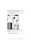
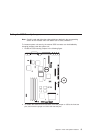
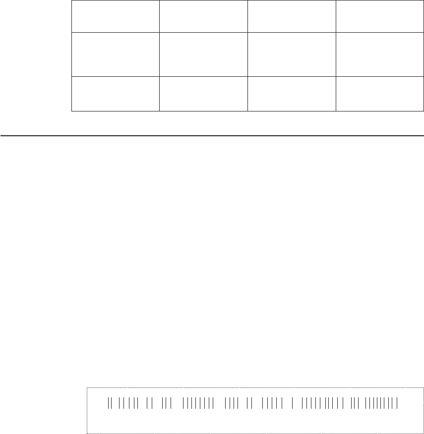
3. Determine the system board assembly part number by noting the white barcode
label attached to the card.
Locate the assembly part number in the leftmost alphanumeric block of characters,
following the first three characters, which are always 11S. In the following example,
the assembly part number is 41L5812.
The FRU part number is in the center alphanumeric block of characters, following
the first three characters which are always FRU. In the following example, the FRU
part number is 41L5912.
11S 2YL1109140246 FRU 90541L581 41L5912
After you have identified both the system board assembly part number and the FRU
part number, see the table in “Determining the Fansink Assembly Number to be
Replaced” on page 1 to determine the appropriate fan to be replaced.
2 Supplement to the Service Guide and User’s Guide