


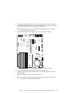
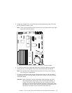

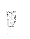

5. Locate and unplug the fan and disconnect the fansink assembly power cable from
the CPU fansink connector (J26).
Note: There are two possible fansink connections for this system board: right-angle
finger tabs, and wire springs.
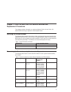
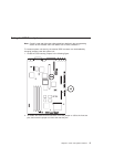
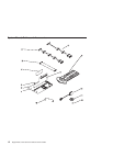
Fansink Location
6. To remove a fansink with right-angle finger tabs, unclip the heatsink by pushing
down and away on the fingertab. Remove the fansink assembly and discard.
Note:
Do not
wipe off the remaining thermal grease from the top of the existing
CPU chip on the systemboard.
7. To remove a fansink with wire springs, push down and away on the wire loop to
disengage the fansink assembly. Gently lift the fansink vertically up and off without
rocking the fansink.
Attention: While removing the closed loop fansink, severe damage may occur
which would require replacing the entire system board assembly. To
minimize the risk for system damage, be sure to perform the above
operation
no less than 30 seconds after powering off the system
, while
the heatsink is still hot. Warm adhesive between the heatsink and CPU
chip will be less likely to pull the aluminum cap off the chip.
Chapter 1. 7043–140 and 7043–150 Fansink Removal and Replacement Procedures 5