


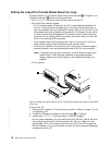

Setting the Loop ID to Provide Additional Loop IDs
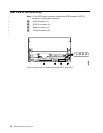
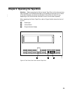
If Feature Switch 3 on the Ultrium Tape Drive is set to ON (see 1 in Figure 6 on
page 16), the LID/status connector 2 has the following definition:
v Pins 1 through 7 are used to set the LID.
v Pin 8 overrides pins 1 through 7. If pin 8 is jumpered, the drive will use its vital
product data (VPD) to set the AL_PA. The enclosure can set the AL_PA in VPD
through the RS-422 interface.
v Pin 9 is ground.
Note: Feature Switch 3 does not support LEDs on an enclosure. Therefore, when
Feature Switch 3 is set to ON, the drive can report Fibre Channel problems
(error codes 8 and F) on the single-character display, but not by using the
enclosure’s external indicators.
To set the AL_PA:
1. Determine an unused AL_PA address for the drive and refer to Table 4 for its
corresponding LID.
2. Locate the LID/status connector on the drive (see 2 in Figure 6 on page 16).
3. Jumper pins 1 through 8 as shown in Table 4.
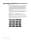
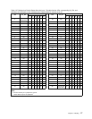
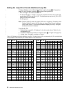
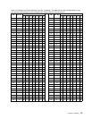
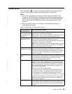
Table 4. ID Settings that Provide Additional Loop IDs. The table lists the LIDs, corresponding AL_PAs, and definitions
of the jumpers on the connector pins. Feature Switch 3 must be set to ON.
LID AL_PA
PIN
LID AL_PA
PIN
1234567 1234567
0 EF ------- 21 B1 -G----G
1 E8 ------G 22 AE -G---G-
2 E4 -----G- 23 AD -G---GG
3 E2 -----GG 24 AC -G--G--
4 E1 ----G-- 25 AB -G--G-G
5 E0 ----G-G 26 AA -G--GG-
6 DC ----GG- 27 A9 -G--GGG
7 DA ----GGG 28 A7 -G-G---
8 D9 ---G--- 29 A6 -G-G--G
9 D6 - - -G- -G 2A A5 -G-G-G-
A D5 - - -G-G- 2B A3 -G-G-GG
B D4 - - - G - G G 2C 9F - G - G G - -
C D3 ---GG-- 2D 9E -G-GG-G
D D2 - - -GG-G 2E 9D -G-GGG-
E D1 - - - GGG - 2F 9B - G - GGGG
F CE - - - GGGG 30 98 - GG ----
10 CD --G---- 31 97 -GG---G
11 CC --G---G 32 90 -GG--G-
12 CB - - G - - G - 33 8F - G G - - G G
13 CA - - G - - G G 34 88 - G G - G - -
14 C9 - - G - G - - 35 84 - G G - G - G
15 C7 - -G-G-G 36 82 -GG-GG-
16 C6 - - G - GG - 37 81 - GG - GGG
18 IBM Ultrium Internal Tape Drive
|
|
|
|
|
|
|
|
|
|
|
|
|