


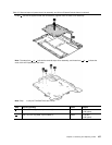
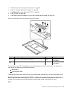
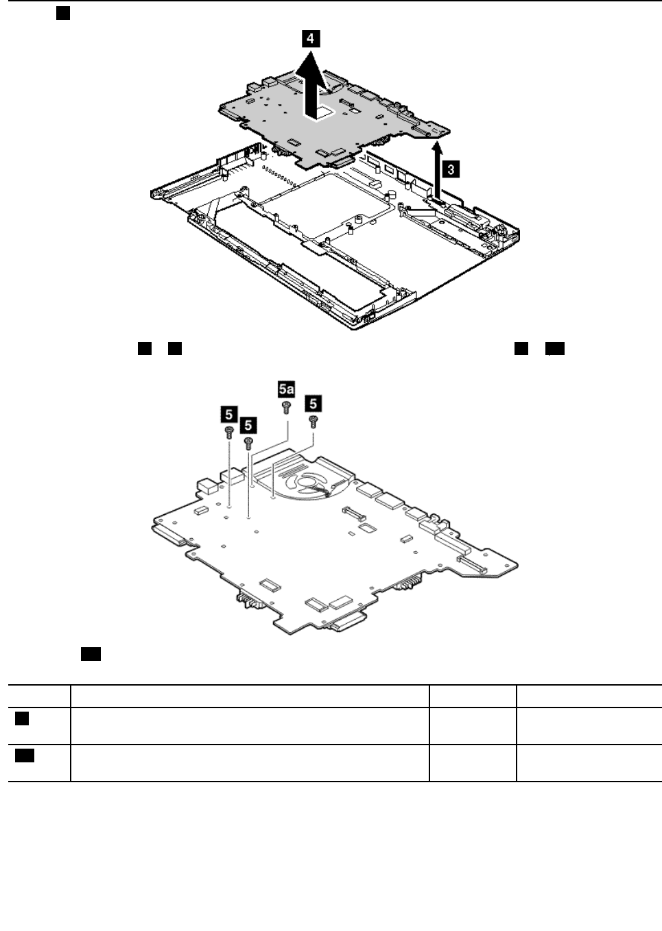
Table 25. Removal steps of system board, fan assembly, and 34-mm ExpressCard slot frame (continued)
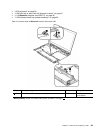
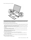
In step
4, remove the system board and fan assembly together from the base cover assembly.
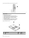
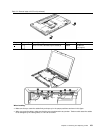
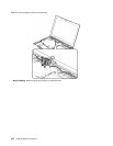
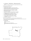
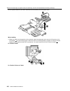
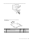
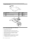
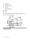
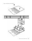
Note: The steps from5to7indicate the removal steps of fan assembly, and those from8to11indicate the
ones of 34-mm ExpressCard slot frame.
Note: Step5ais only for ThinkPad T410s and T410si.
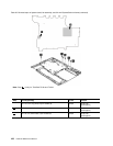
Step Screw (quantity) Color
Torque
5
M2 × 3.5 mm, big-head, nylon-coated (3)
Black 0.181 Nm
(1.85 kgfcm)
5a
M2 × 3.5 mm, big-head, nylon-coated (1)
Black 0.181 Nm
(1.85 kgfcm)
Chapter 8. Removing and replacing a FRU 107